Understanding Capacitive Proximity Sensors
Capacitive proximity sensors are versatile electronic devices used to detect both metallic and non-metallic objects, including liquids, powders, and granular materials. Operating on the principle of capacitance change, these sensors generate an electrostatic field. When a target object enters this field, it alters the capacitance, triggering the sensor's output. This functionality makes them indispensable in various industrial applications, from level detection in tanks to material handling and packaging. Unlike inductive sensors, which only detect metals, capacitive sensors offer broader material compatibility, enhancing their utility in complex automation environments. Their ability to sense through non-metallic containers adds to their adaptability, allowing for non-contact measurement in challenging setups.
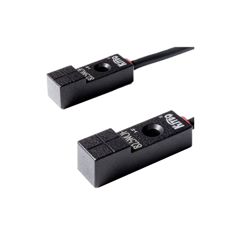
Key Components in the Identification Diagram
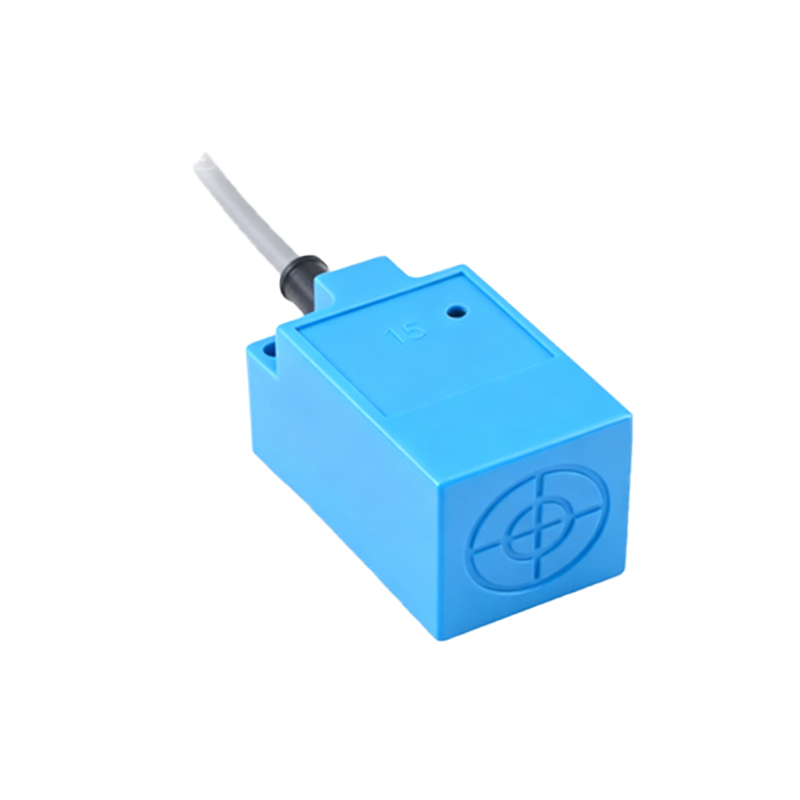
A standard capacitive proximity sensor identification diagram typically includes several critical components labeled for clarity. The sensor body houses the sensing face, often marked with symbols indicating the active area. Electrical connections are shown via terminal points, such as brown (positive), blue (negative), and black (output) wires, following international color codes. The diagram may also depict adjustment potentiometers for sensitivity tuning, allowing users to calibrate the detection range based on material properties. Additionally, LED indicators for power and output status are illustrated, providing visual feedback on operation. Understanding these elements ensures proper installation and troubleshooting, reducing downtime in industrial systems.
Interpreting Symbols and Markings

Symbols on a capacitive proximity sensor diagram convey essential technical specifications. Common markings include the sensing range (e.g., 5-20 mm), denoted in millimeters, and the operating voltage (e.g., 10-30 V DC). Output types, such as NPN (sinking) or PNP (sourcing), are represented with standardized electrical symbols, crucial for compatibility with control systems like PLCs. The diagram might also show shielding indicators, which highlight whether the sensor is shielded (flush-mountable) or unshielded (non-flush), affecting installation proximity to metal surfaces. Environmental ratings, like IP67 for dust and water resistance, are often included to ensure suitability for harsh conditions. Mastery of these symbols aids in selecting the right sensor for specific applications.
Wiring and Connection Guidelines
Proper wiring is vital for optimal sensor performance, as detailed in identification diagrams. Diagrams illustrate the connection of power supply lines to the sensor's terminals, emphasizing correct polarity to prevent damage. For output configurations, three-wire setups are standard, with the black wire typically carrying the signal to a load device like a relay or controller. Some diagrams include examples of series or parallel connections for multiple sensors, along with protective measures such as fuses or surge suppressors. Following these guidelines minimizes electrical interference and ensures reliable detection, especially in noisy industrial environments where stray capacitance can affect accuracy.
Calibration and Sensitivity Adjustment
Identification diagrams often feature calibration sections, showing how to adjust sensitivity via a potentiometer or digital interface. This adjustment compensates for different target materials, such as plastics versus liquids, by modifying the capacitance threshold. Diagrams may include step-by-step visuals, like turning a screw to increase or decrease the sensing distance, accompanied by notes on avoiding over-sensitivity to background objects. Regular calibration, as per diagram instructions, maintains precision over time, preventing false triggers in applications like fill-level control or object counting. This process is key to leveraging the sensor's full capability across diverse operational scenarios.
Common Applications and Practical Tips
Capacitive proximity sensors are widely used in industries like food processing, pharmaceuticals, and automotive manufacturing. Identification diagrams help users implement them for tasks such as liquid level sensing in transparent tubes or detecting cardboard in packaging lines. Practical tips from diagrams include maintaining a clean sensing face to avoid contamination, ensuring adequate mounting distance from metal to reduce interference, and verifying environmental limits. For instance, diagrams might recommend using non-metallic brackets in humid areas to prevent corrosion. By adhering to these insights, engineers can enhance system efficiency and longevity, making capacitive sensors a reliable choice for automated processes.
Troubleshooting Based on Diagram Indicators
When issues arise, identification diagrams serve as troubleshooting tools. They outline diagnostic steps, such as checking LED patterns—steady on for power, blinking for detection—to identify faults like wiring errors or target misalignment. Diagrams may list common problems, such as reduced sensing range due to material changes, and solutions like recalibrating sensitivity. Electrical tests, like measuring output voltage with a multimeter, are often depicted to verify functionality. Utilizing these resources enables quick resolution of operational hiccups, ensuring minimal disruption in production lines and maintaining high reliability in industrial settings.