Introduction to Origin Proximity Switch Sensors
Origin proximity switch sensors are fundamental components in industrial automation, widely used for position detection, counting, and speed monitoring. These non-contact sensors detect the presence or absence of a target object without physical contact, ensuring high reliability and longevity. They are commonly found in machinery, conveyor systems, and robotic applications. Understanding their wiring is crucial for proper installation, functionality, and safety. This guide provides a detailed overview of the wiring diagrams for typical origin proximity sensors, covering various types and configurations.
Types of Origin Proximity Sensors
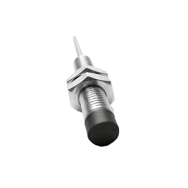
There are several types of origin proximity sensors, primarily categorized by their sensing technology. Inductive proximity sensors detect metallic objects using an electromagnetic field, while capacitive sensors can detect both metallic and non-metallic materials. Photoelectric sensors use light beams for detection. Each type has specific wiring requirements based on its output configuration, such as NPN (sinking) or PNP (sourcing) outputs. Additionally, sensors may have 2-wire, 3-wire, or 4-wire setups, influencing how they connect to power supplies and control devices like PLCs (Programmable Logic Controllers).
Basic Wiring Principles and Components
A standard wiring setup for an origin proximity sensor involves connecting it to a power source and a load. The power source typically provides DC voltage, commonly 12-24V DC, though AC versions exist. Key components include the sensor itself, power supply wires, load wires (connecting to devices like relays or PLC inputs), and sometimes a ground wire for shielding. The wiring diagram illustrates these connections clearly, showing the positive (V+), negative (V-), and output terminals. Proper polarity must be observed to prevent damage. For instance, in a 3-wire DC sensor, the brown wire is usually for positive voltage, blue for negative, and black for the output signal.
Detailed Wiring Diagram for 3-Wire DC Sensors
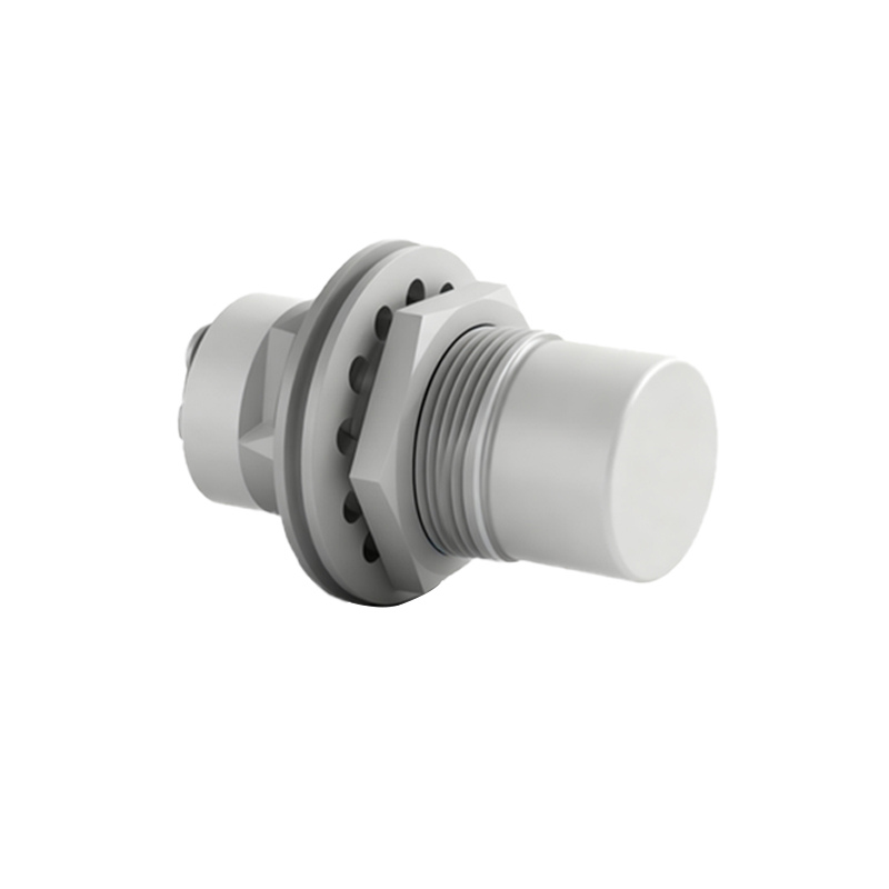
The 3-wire DC origin proximity sensor is the most common in industrial settings. For an NPN type, the wiring diagram shows the brown wire connected to the positive terminal of the power supply, the blue wire to the negative terminal, and the black output wire to the load, which is then linked to the positive side. In a PNP type, the brown and blue wires connect similarly, but the black output wire attaches to the load, which then connects to the negative side. This configuration ensures the sensor switches the output relative to the common ground. Always refer to the manufacturer's datasheet for specific wire colors and terminal designations, as they can vary.
Wiring for 2-Wire and 4-Wire Sensors
2-wire sensors simplify wiring by combining power and load connections into two wires, making them easy to install but less precise in some applications. They can be used in both AC and DC circuits, with the wiring diagram showing direct series connection between the power supply, sensor, and load. 4-wire sensors often include two output channels (e.g., one NPN and one PNP) or additional diagnostic features, providing more flexibility. Their diagrams detail separate wires for power, ground, and multiple outputs, allowing for complex control scenarios. Ensure correct voltage matching to avoid malfunctions.
Connection to PLCs and Control Systems
Integrating origin proximity sensors with PLCs requires careful wiring to match input module specifications. For a PLC with a sinking input module, an NPN sensor is suitable, where the sensor output connects to the PLC input and common ground. For sourcing input modules, a PNP sensor is used, with the output linked to the input and positive voltage. The wiring diagram should include terminals for the PLC's power supply, input points, and sensor connections. Use shielded cables to reduce electrical noise interference, especially in environments with motors or high-frequency devices, and ground the shield properly at one end.
Safety Considerations and Troubleshooting
Safety is paramount when wiring origin proximity sensors. Always disconnect power before installation to prevent electric shock or short circuits. Follow local electrical codes and use appropriate wire gauges for the current load. Common issues include incorrect polarity, loose connections, or voltage mismatches, leading to sensor failure or erratic behavior. Troubleshooting steps involve checking continuity with a multimeter, verifying power supply levels, and inspecting for physical damage. Regular maintenance, such as cleaning sensor faces and tightening terminals, ensures long-term reliability and prevents downtime in automated systems.
Conclusion and Best Practices
Mastering the wiring of origin proximity switch sensors is essential for efficient industrial operations. Always start by reviewing the sensor's datasheet and wiring