Understanding Proximity Sensor Connector Types
Proximity switch sensors are fundamental components in industrial automation, and their connectors are critical for reliable signal transmission and power supply. The images of these connectors provide essential visual information for selection, installation, and troubleshooting. Common connector types visible in such images include M8, M12, and M23 threaded connectors, which are standardized for industrial environments. M12 connectors, often with 3, 4, or 5 pins, are the most prevalent for standard DC sensors. Images typically showcase the metal or plastic housing, the pin configuration, the threaded coupling nut, and the cable outlet style (straight or right-angled). High-resolution pictures allow engineers to verify the keying (coding) of the connector, which prevents mismating between devices of different voltages or signal types, such as PNP versus NPN outputs. Close-up shots are invaluable for identifying the IP (Ingress Protection) rating from physical seals and gaskets.
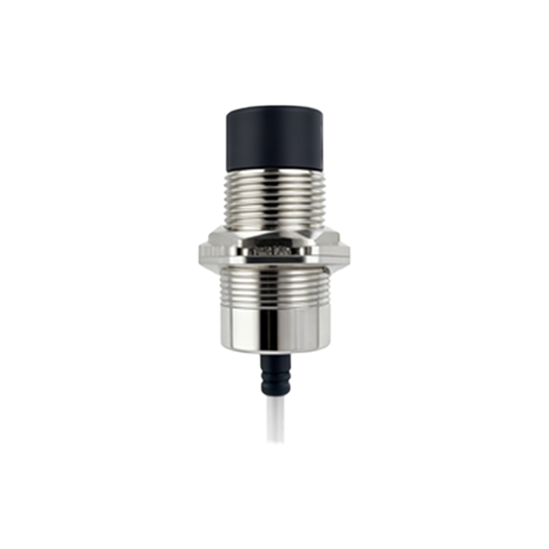
Deciphering Wiring and Pin Configuration from Photos
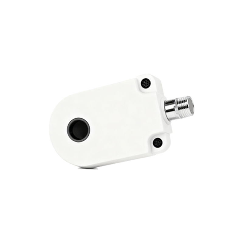
A clear connector image is a direct wiring guide. For a standard 3-wire DC proximity sensor (brown, blue, black wires), a detailed photo will show the pin assignment within the connector housing. The brown wire (pin 1) is typically for positive supply (+V), blue (pin 3) for negative/0V, and black (pin 4) for the switched output signal. Images often include diagrams or color-coding on the connector body itself. Engineers rely on these visuals to confirm the sensor's output type before integration into a control system. Photos can also reveal if the connector is pre-wired (with a flying lead) or is a quick-disconnect (QD) style, where the sensor body and cable connector are separate. This distinction, clear in imagery, impacts maintenance and replacement procedures.

Identifying Connector Materials and Build Quality
The durability of a proximity sensor's connection point is paramount. High-quality images reveal the construction materials. Metal connectors, usually nickel-plated brass, offer superior electromagnetic shielding and mechanical strength, suitable for harsh environments. Plastic connectors, often made from PUR or PVC, provide good chemical resistance and are more cost-effective. Images can show critical details like the quality of the strain relief, the integrity of the overmolding where the cable enters the connector, and the presence of sealing rings. Zoomed-in photos can expose defects, poor molding, or substandard materials, enabling procurement teams to assess supplier quality before purchase.
The Role of Connector Images in System Integration
During the design and integration phase of a control panel or machine, connector images are used for planning cable routing and selecting mating receptacles. A picture showing a right-angled connector versus a straight one directly influences the spatial layout in a tight control cabinet. Images also help identify the mating counterpart—whether it's a standard socket, a junction box port, or a specific PLC input module connector. Furthermore, for sensors with advanced diagnostics or IO-Link capability, connector images (often showing 5-pin M12) provide immediate visual differentiation from standard 3-pin or 4-pin types, preventing configuration errors.
Utilizing Images for Maintenance and Troubleshooting
In maintenance scenarios, a connector image serves as a benchmark. Technicians can compare the installed sensor's connector with a reference image to check for physical damage, corrosion, bent pins, or moisture ingress. Photos illustrating common failure points, such as cracked strain reliefs or worn threading, are excellent training tools. For replacement, an accurate image ensures the correct connector type is ordered, matching the thread size, pin count, and keying code. Side-by-side comparison images of different coding types (A-coded for sensors, B-coded for fieldbus, etc.) are particularly useful for preventing downtime caused by incorrect parts.
Best Practices for Sourcing and Specifying Based on Imagery
When creating specifications or sourcing components, demanding high-quality, standardized connector images from datasheets or suppliers is a best practice. These images should include scale, multiple angles (front, side, rear), and clear shots of any markings. Engineers should cross-reference the connector image with the sensor's technical drawing for dimensions. In global projects, images provide a universal language that transcends textual specifications, ensuring all parties have a clear, unambiguous understanding of the physical interface required. Always verify that the connector in the image matches the part number and description in the accompanying documentation.