Introduction to Waterproof Fog Photoelectric Sensors
In industrial and automotive applications, environmental factors like water, fog, and dust pose significant challenges to sensor reliability. A waterproof fog photoelectric sensor is specifically engineered to maintain precise detection capabilities under such adverse conditions. The core principle remains based on photoelectric sensing, where a light emitter and receiver work in tandem. However, the schematic diagram reveals critical additional components and design considerations that differentiate it from standard photoelectric sensors. The primary goal of the schematic is to illustrate how the sensor achieves immunity to moisture ingress and condensation, ensuring stable operation in environments with high humidity, direct water exposure, or rapid temperature changes that cause fogging on optical surfaces. Understanding this schematic is essential for engineers integrating these robust sensors into outdoor machinery, agricultural equipment, washdown areas in food processing, or vehicle safety systems.
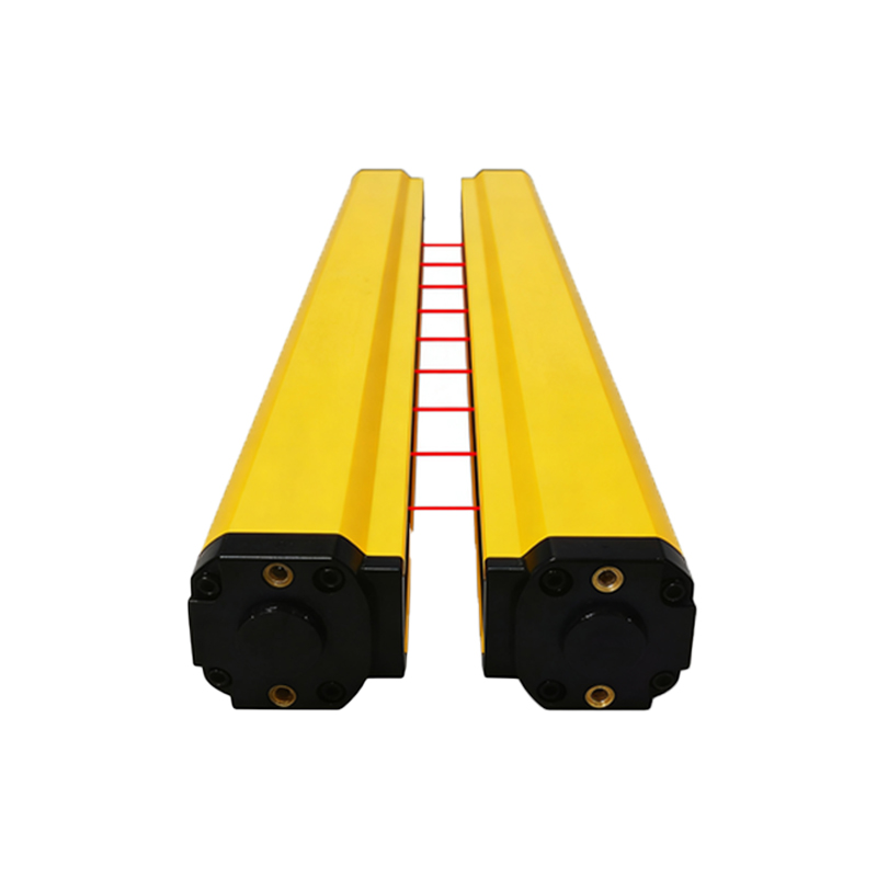
Core Photoelectric Sensing Circuitry
At the heart of the schematic lies the fundamental photoelectric circuit. This typically involves an infrared LED as the light emitter. The driving circuit for the LED includes a constant current source to ensure consistent light output intensity, which is crucial for maintaining sensitivity despite potential long-term use or voltage fluctuations. Opposite the emitter, a phototransistor or photodiode acts as the receiver. Its output is connected to a high-gain amplifier circuit, often an operational amplifier configured in a transimpedance arrangement. This converts the minute photocurrent generated by the receiver into a usable voltage signal. A comparator stage then follows, comparing this amplified signal to a preset threshold voltage to generate a clean, digital ON/OFF output. This basic detection loop is the foundation upon which the waterproof and anti-fog features are built.
Sealing and Housing Design in the Schematic
While a schematic primarily shows electrical connections, a comprehensive diagram for this sensor type includes notes or symbols representing mechanical and material specifications critical for waterproofing. Key notations often point to the optical interface. The lens covering both the emitter and receiver is a specialized component. The schematic may denote the use of hydrophobic coatings on the lens surface, represented by a specific symbol or note. This coating causes water droplets to bead up and roll off, preventing the formation of a continuous water film that could refract or block the light beam. Furthermore, the schematic will detail the O-ring seals, typically indicated at the junction between the lens assembly and the sensor body, and at the cable gland entry point. These seals are crucial for achieving IP67, IP68, or IP69K ratings, ensuring the housing remains impervious to water and dust under specified pressures and durations.
Anti-Fogging and Internal Climate Control
Preventing internal fogging is a distinct challenge addressed in the sensor's design. The schematic may reveal features for internal climate control. One common approach is the inclusion of a desiccant chamber or breather valve within the housing, often symbolized as a separate component connected to the internal air volume. This element regulates humidity inside the sealed unit, absorbing moisture that could otherwise condense on the inner surface of the lens during temperature cycles. In more advanced designs, the schematic might show a small, integrated heating element circuit. This low-power heater, strategically placed near the optical components, maintains the lens temperature slightly above the ambient dew point, effectively preventing condensation from forming. The power management for this heater, ensuring it doesn't interfere with the sensing circuitry, is a key part of the electronic design shown in the diagram.
Signal Integrity and Noise Immunity
Environmental interference like water droplets or a film of fog can cause signal scattering and attenuation. The schematic reflects design choices to combat this. Modulation and synchronous detection are frequently employed. The diagram will show an oscillator circuit modulating the emitted IR light at a specific frequency (e.g., several kHz). The receiver circuit is then coupled with a band-pass filter or a synchronous demodulator tuned to the same frequency. This technique, clearly illustrated in the signal processing chain of the schematic, makes the sensor highly immune to ambient light (sunlight, room lights) and only responsive to its own modulated signal. Even if water or fog reduces signal strength, the synchronous detection ensures reliable recognition of the presence or absence of the true beam, minimizing false triggers.
Output Stage and Protection Circuits
The final section of the schematic details the output interface and protective measures. The output is typically a solid-state switch (NPN/PNP transistor) or a relay driver, providing a robust signal to PLCs or controllers. Crucially, the schematic includes comprehensive protection circuits. These often involve TVS (Transient Voltage Suppression) diodes at the power supply inputs to guard against voltage spikes. Reverse polarity protection, using a series diode or a MOSFET-based circuit, is also standard. For sensors with analog current outputs (4-20mA), the schematic shows a precision current loop regulator designed to maintain signal accuracy despite cable resistance or minor power variations. These protections ensure the sensor's electronic core remains safe from electrical faults, complementing the physical ruggedness provided by the waterproof housing.
Integration and Application Considerations
A complete schematic package includes application notes that guide integration. It specifies voltage requirements (commonly 10-30V DC), output types, and connection pinouts. The diagram emphasizes the importance of proper cable management; even with a waterproof sensor body, the integrity of the cable and its connection to the control panel must be maintained using appropriate conduits or seals. The schematic also implies performance characteristics: increased sensing range may be required to compensate for potential signal loss in heavy fog or rain, and the response time is designed to remain stable. By studying the schematic, an engineer can select the correct model, plan the electrical integration, and understand the maintenance points, ensuring the sensor delivers long-term, reliable performance in demanding wet and foggy environments.