Understanding the Basic Components
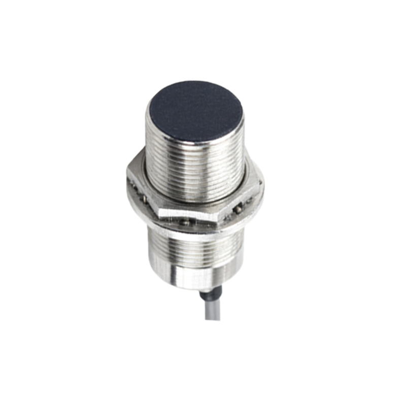
A proximity switch sensor is a non-contact electronic device that detects the presence or absence of an object within its sensing range. It operates by emitting an electromagnetic field or a beam of electromagnetic radiation and looking for changes in the field or return signal. The output from these sensors is typically a switching signal—either a digital ON/OFF (like NPN or PNP transistor outputs) or a relay contact closure. The light, in this context, is usually an indicator lamp, such as an LED or an incandescent bulb, which serves to provide a visual signal based on the sensor's detection state. The core principle involves using the sensor's output to control the electrical circuit powering the light, thereby illuminating it when a target object is detected and turning it off when the object moves away.
Selecting the Appropriate Sensor and Light
Before proceeding with the connection, it is crucial to ensure compatibility between the proximity sensor and the light. First, identify the sensor's output type. Common types include NPN (sinking) and PNP (sourcing) for DC sensors, and relay or solid-state outputs for AC/DC variants. Check the sensor's datasheet for its output voltage and current ratings. Similarly, verify the light's specifications, including its operating voltage (e.g., 12V DC, 24V DC, 120V AC) and current draw. The sensor's output must be capable of handling the light's current requirement; if not, an intermediate relay or amplifier may be necessary. For instance, a low-current sensor output cannot directly drive a high-power incandescent lamp without risking damage.
Wiring a DC Proximity Sensor to a DC Light
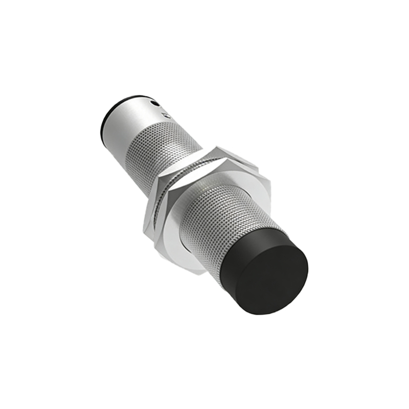
For a typical DC circuit, start by ensuring a stable DC power supply matches both the sensor and light's voltage ratings (e.g., 24V DC). Connect the positive terminal of the power supply to the sensor's positive supply wire (usually brown or red). Connect the negative terminal of the power supply to both the sensor's negative supply wire (usually blue or black) and one terminal of the light. Next, connect the sensor's output wire (often black for NPN or white for PNP) to the other terminal of the light. In an NPN configuration, the output acts as a switch to ground; when the sensor detects an object, it connects the output to ground, completing the circuit and turning the light on. In a PNP setup, the output switches positive voltage to the light. Always double-check polarities to prevent short circuits.
Connecting an AC Proximity Sensor to an AC Light
When working with AC components, safety is paramount—ensure the power is disconnected during wiring. AC proximity sensors often have relay outputs or triac outputs. For a simple relay output sensor, connect one AC power line (e.g., hot wire) to the sensor's common (C) terminal. Connect the sensor's normally open (NO) terminal to one terminal of the AC light. Then, connect the other terminal of the light to the neutral wire of the AC power supply. When the sensor activates, the relay closes, allowing current to flow through the light and illuminate it. If the light is high-power, verify the sensor's relay contact rating can handle the load. Use appropriate wire gauges and enclosures to meet electrical codes.
Incorporating Protective Measures and Testing
To ensure reliability and longevity, incorporate protective devices such as fuses or circuit breakers in the power supply line. For DC circuits, a flyback diode across the light may be needed to suppress voltage spikes from inductive loads. For AC circuits, consider using a surge protector. After wiring, perform a thorough inspection: check for loose connections, ensure insulation is intact, and verify that all components are securely mounted. Apply power and test the system by introducing a target object within the sensor's range. The light should respond promptly—turning on upon detection and off when the object is removed. If the light fails to operate, recheck wiring against the sensor's diagram and measure voltages with a multimeter to diagnose issues like open circuits or insufficient current.
Advanced Configurations and Applications
Beyond basic on/off control, proximity sensors can be integrated into more complex lighting systems. For example, multiple sensors can be connected in series or parallel to control a single light based on various conditions, such as in conveyor belt monitoring. Alternatively, a sensor can interface with a programmable logic controller (PLC) or microcontroller, which then controls the light, allowing for timed sequences or logic-based operations. In industrial settings, this setup is common for machine status indication or safety