Introduction to Photoelectric Sensors and PLC Integration
Photoelectric sensors are indispensable components in modern industrial automation, providing non-contact detection of objects based on light beam interruption or reflection. Their applications range from simple object presence detection to complex positioning and counting tasks. To maximize their utility, these sensors must interface effectively with the brain of the control system: the Programmable Logic Controller (PLC). While some sensors offer direct PLC-compatible outputs, many standard models require an intermediary device for safe and reliable signal conditioning. This is where electromechanical relays play a critical role, serving as a robust and versatile bridge between the sensor's switching circuit and the PLC's input module.
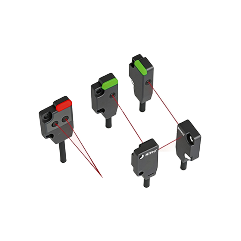
The Role of Relays as Interface Components
A relay is an electrically operated switch. In the context of connecting a photoelectric sensor to a PLC, it acts as an isolation and amplification device. The sensor's output, typically a transistor (PNP or NNP) operating at a low current (e.g., 100-200mA), is used to control the relay coil. When the sensor detects an object, it energizes the coil, which mechanically closes or opens the relay's contact set. This contact set is then wired directly to the PLC's digital input card. The primary advantages are clear: electrical isolation protects the sensitive PLC input from voltage spikes or noise originating in the sensor's power circuit, and the relay contacts can handle a wider range of voltages and currents required by the PLC input, regardless of the sensor's native output specifications.
Standard Wiring Configuration and Circuit Design
A typical wiring setup involves a three-wire DC photoelectric sensor (Brown wire: +24V DC, Blue wire: 0V DC, Black wire: Output). The sensor's output (Black wire) is connected to one terminal of the relay coil. The other coil terminal is connected to the 0V DC line. A suppression diode (like a 1N4007) is wired in reverse bias across the coil terminals to protect against back-electromotive force (back-EMF) generated when the coil de-energizes. The relay's common (COM) and normally open (NO) contacts form the signal path to the PLC. One side is connected to a positive voltage source referenced for the PLC inputs (often +24V DC), and the other side is connected to the specific PLC input terminal (e.g., I0.0). The PLC input common is connected to 0V DC. This configuration ensures that when the sensor activates, the relay pulls in, closing the NO contact, sending the +24V signal to the PLC input, which the PLC program interprets as a logic HIGH or TRUE state.
Key Considerations for Reliable Operation
Selecting the correct relay is paramount. Engineers must consider the coil voltage (must match the sensor's output voltage and current capability), contact rating (must be sufficient for the PLC input's required voltage and minimal current, often as low as 5-10mA), and the relay's physical form (plug-in or PCB mount). Environmental factors like temperature, humidity, and vibration resistance should align with the application. Additionally, for high-speed counting applications, the relay's operational speed (mechanical life and bounce time) may become a limiting factor compared to solid-state alternatives. Proper enclosure and wiring practices are essential to prevent electromagnetic interference (EMI) from disrupting the signal. Regular maintenance checks should include verifying the mechanical action of the relay and checking for contact pitting or carbon buildup over time.
Advantages Over Direct Connection Methods
Using a relay interface offers several benefits beyond basic isolation. It provides exceptional flexibility; the same type of sensor can be used with PLCs from different manufacturers that may have different input circuit requirements (sinking vs. sourcing). It allows for signal inversion simply by using the normally closed (NC) relay contact instead of the NO. Furthermore, a single sensor output can be used to drive multiple relays, enabling one detection event to send signals to multiple PLC inputs or even other devices simultaneously. This method also simplifies troubleshooting, as the relay's physical state (often with an indicator LED) provides a clear, visible confirmation of the sensor's activation status, independent of the PLC's diagnostics.
Common Application Scenarios in Industry
This sensor-relay-PLC architecture is ubiquitous. A classic example is in conveyor belt systems, where a photoelectric sensor detects packages arriving at a sorting station. The sensor triggers a relay, whose contact signals the PLC. The PLC then executes a sequence to activate a diverter arm. In automated packaging machinery, sensors detect the position of products on a filling line via relays before the PLC initiates a sealing cycle. In palletizing cells, multiple photoelectric sensors, each through its own relay, provide positional feedback to the PLC to coordinate the robotic arm's stacking pattern. This approach is also common in safety-interlock circuits, where a sensor guarding a access door uses a relay to provide a hardwired stop signal to the PLC's safety input module.
Troubleshooting and Best Practices
When a detection failure occurs, a systematic approach is required. First, verify the sensor's operation independently by checking its built-in indicator LED. Next, confirm the relay coil is energizing (audible click, indicator light) when the sensor activates. If the coil activates but the PLC does not register the input, use a multimeter to check for voltage at the PLC terminal when the relay contact is closed. Common issues include incorrect wiring (sinking vs. sourcing mismatch), blown fuses on the control voltage line, welded relay contacts stuck closed, or excessive voltage drop across long wire runs. Best practices include using clearly labeled wiring diagrams, implementing master control relays for emergency stops, and providing test points in the control panel for key signals to facilitate rapid diagnostics and minimize machine downtime.