Introduction to PNP Switching Technology
In the realm of industrial automation and control systems, the choice between PNP and NPN sensor outputs is fundamental. PNP, standing for Positive-Negative-Positive, refers to a specific type of bipolar junction transistor configuration used within the sensor's output circuit. A PNP proximity switch or sensor is characterized by its switching behavior: it actively switches the positive supply voltage to the output line when the target is detected. This design means that in a typical wiring scheme, the load (such as a PLC input, relay, or indicator lamp) is connected between the sensor's output wire and the common negative (0V) rail. This "sourcing" functionality is a key identifier and a primary reason for its widespread adoption in many global regions, particularly in Europe and Asia.
Operating Principle of PNP Proximity Sensors
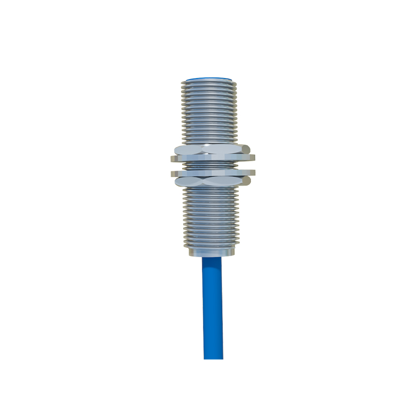
The core function of a PNP proximity sensor is non-contact detection. Inductive types generate an electromagnetic field and detect the presence of metallic objects by changes in oscillation. Capacitive versions can detect both metallic and non-metallic materials by sensing changes in capacitance. Photoelectric sensors use light beams to detect objects. Regardless of the sensing technology, the internal electronic circuitry culminates in a PNP transistor output stage. When no target is present, the output transistor is in an "off" state, and the output wire is effectively disconnected from the positive supply. Upon detection, the transistor switches "on," connecting the output line to the positive supply voltage (e.g., +24V DC), thus sourcing current to the connected load.

Wiring and Electrical Characteristics
Correct wiring is crucial for reliable operation. A standard three-wire DC PNP sensor has brown (or red), blue, and black wires. The brown wire connects to the positive DC supply voltage (+V, typically +24V). The blue wire connects to the power supply common or 0V. The black wire is the switched output signal. When active, the black wire sources +24V. The load is connected between this black wire and the 0V rail. This configuration offers advantages in noise immunity, as the signal transitions between a high voltage (+V) and an open state, which is less susceptible to electromagnetic interference compared to low-voltage switching near 0V.
Key Advantages in Industrial Applications
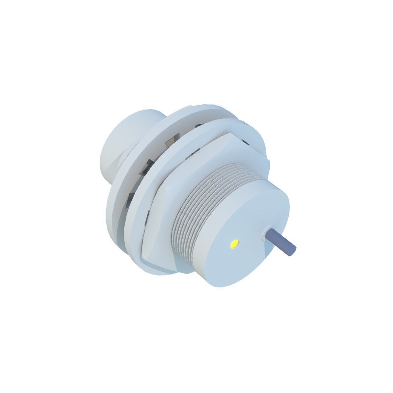
PNP sensors offer several compelling benefits. Their compatibility with many modern Programmable Logic Controllers (PLCs) is a major factor, as numerous PLC digital input modules are designed to be activated by a sourcing (PNP) signal. The wiring scheme often aligns intuitively with control panel layouts, where commons are frequently tied to the negative rail. From a safety and diagnostic perspective, a "wire break" or power loss in a PNP circuit typically results in an "off" signal (0V at the load), which can be engineered to represent a safe state in many machinery applications. This fail-safe characteristic is highly valued.
Comparison with NPN Sensor Outputs
Understanding PNP is incomplete without contrasting it with NPN (sinking) sensors. The difference is not in sensing quality but in the output circuit's electrical path. An NPN sensor switches the negative or 0V line to the load. In practice, this means the load must be connected between the positive supply and the sensor's output wire. While PNP sources current from the output, NPN sinks current into the output. The choice often depends on regional standards, PLC input card design, and existing control architecture. Mixing PNP and NPN devices incorrectly in a circuit will result in malfunction.
Selection Criteria and Best Practices
Selecting the right PNP sensor involves multiple parameters. First, define the sensing type: inductive for metals, capacitive for various materials, or photoelectric for long-range or precise detection. Consider the sensing range, rated operating voltage (commonly 10-30V DC), output current capacity, and switching frequency. Environmental factors like temperature, humidity, and potential chemical exposure dictate the required housing material (e.g., stainless steel, PBT plastic) and ingress protection (IP) rating. For wiring, always refer to the manufacturer's datasheet, use shielded cables in electrically noisy environments, and ensure proper grounding.
Common Applications and Use Cases
PNP proximity switches are ubiquitous in automated systems. They are used for precise position detection of machine parts, such as cylinders (via built-in magnets), conveyor pallets, or robotic arms. They act as counters on production lines, detect the presence or absence of components in assembly stations, and provide end-of-travel limits for moving machinery. In packaging, PNP photoelectric sensors detect labels