Understanding the OS10 Photoelectric Sensor
The OS10 series represents a versatile line of photoelectric sensors widely utilized in industrial automation for detection, counting, and positioning tasks. These sensors operate by emitting a light beam—typically infrared, visible red, or laser—and detecting changes in the received light caused by the presence or absence of an object. The OS10 models are known for their robust construction, reliable performance in challenging environments, and straightforward integration into control systems. A proper understanding of their electrical characteristics and wiring configurations is fundamental to ensuring optimal functionality and longevity in applications ranging from packaging machinery to material handling systems.
Electrical Specifications and Pin Configuration
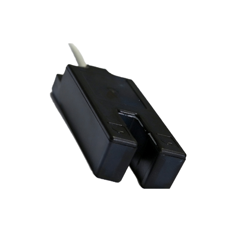
Before commencing any wiring procedure, it is crucial to consult the specific datasheet for your OS10 model variant (e.g., diffuse, retro-reflective, or through-beam). Generally, these sensors are available in both DC (10-30V DC) and AC (90-250V AC) versions. The standard connection interface involves a pre-wired cable or a quick-disconnect plug with typically four color-coded wires: Brown, Blue, Black, and White. The Brown wire is universally designated for the positive supply voltage (L+ for DC, L1 for AC). The Blue wire is always connected to the common negative or neutral (L- for DC, N for AC). The Black wire serves as the output signal line (normally open or normally closed switching output), and the White wire is often a complementary output or function wire, used for options like an opposite switching logic, teach-in functionality, or a second output. Some models may have only three wires (Brown, Blue, Black), combining the functions.
Standard Wiring Procedure for DC Models
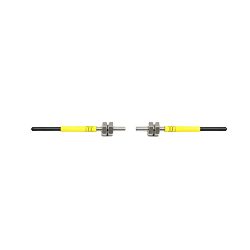
For a standard 3-wire DC NPN sinking output OS10 sensor, follow this sequence. First, ensure the power to the control circuit is completely isolated. Connect the Brown wire to the positive terminal of your 10-30V DC power supply. Connect the Blue wire to the negative terminal (0V) of the same power supply. The Black output wire is then connected to the load. The other side of the load must be connected to the positive supply voltage. For a PNP sourcing output model, the wiring is similar, but the Black output wire connects to the load, and the other side of the load is connected to the negative supply (0V). Always incorporate a protective fuse (e.g., 1A) in the supply line and consider using a shielded cable in electrically noisy environments, grounding the shield at the controller end only.
Wiring Considerations for AC Models and Load Connections
Wiring an AC-powered OS10 sensor requires attention to alternating current safety. Connect the Brown wire to the phase line (L1) of your 90-250V AC supply. Connect the Blue wire to the neutral line (N). The Black output wire is connected in series with the load (such as a relay coil, contactor, or PLC AC input module), and the other terminal of the load is connected back to the neutral line. It is imperative to verify that the sensor's switching capacity (maximum load current) is not exceeded by the connected load. For inductive loads like relays, employing a surge suppressor (RC network or varistor) across the load is highly recommended to protect the sensor's solid-state switch from voltage transients generated during switch-off.
Integrating with Programmable Logic Controllers (PLCs)
Integration with a PLC is a common application. For a DC sensor connected to a DC input module, identify whether the PLC input is sinking or sourcing. Match this with the sensor's output type (NPN or PNP) to ensure compatibility. For an NPN sensor (sinking output), the Black wire connects to the PLC input point, and the PLC input's common is connected to positive voltage. For a PNP sensor, the Black wire connects to the PLC input, and the input common is connected to 0V. Always ensure the sensor's supply voltage matches the PLC system's power. For discrete wiring, use the correct terminal on the PLC's input card as per the manufacturer's manual. Proper grounding of all equipment to a common earth point is essential to minimize electrical noise interference.
Installation, Alignment, and Troubleshooting Tips
Correct mechanical installation and optical alignment are as critical as electrical wiring. Mount the sensor securely to minimize vibration. Use the sensor's alignment indicator (usually an LED) to fine-tune its position for a stable detection signal. Avoid mounting in direct sunlight or in front of highly reflective backgrounds that could cause false triggering. For through-beam types, ensure the emitter and receiver are precisely aligned. Common wiring-related issues include no output signal, which may stem from incorrect power polarity, insufficient voltage, an overloaded output, or a wiring fault. A constantly activated output could indicate incorrect wiring of the function wire (White) or a short circuit. Always use a multimeter to verify supply voltage and output switching behavior during setup and diagnostics.
Safety and Compliance Standards
Adherence to international safety and EMC standards is non-negotiable in industrial settings. The OS10 sensors are designed to comply with standards such as IEC/EN 60947-5-2. When wiring, follow all applicable local and national electrical codes (e.g., NEC, IEC 60204-1). Implement proper lock-out/tag-out procedures before working on circuits. Use cables with appropriate gauge and insulation ratings for the operating voltage and current. Ensure all connections are tight and protected from strain, moisture, and chemical exposure. Proper wiring not only guarantees safe operation but also enhances system reliability and reduces downtime, contributing to overall operational efficiency.