Introduction to 3-Wire DC Proximity Sensors
Three-wire DC proximity sensors are fundamental components in industrial automation, renowned for their reliability in detecting the presence or absence of metallic objects without physical contact. Unlike their two-wire counterparts, these sensors offer superior performance with separate power supply and output signal lines, minimizing residual current and enabling compatibility with a wide range of programmable logic controllers (PLCs) and other control systems. The standard color coding of the connecting wires—typically red, black, and blue—serves as a universal guide for correct installation and operation across global markets. Understanding the function of each wire is critical for ensuring system safety, optimizing sensor performance, and preventing costly wiring errors that could lead to equipment malfunction or downtime.
Decoding the Wire Color Standards
The international standard IEC 60947-5-2 provides guidance on the color coding for the leads of proximity sensors, promoting consistency and safety. For a standard 3-wire DC sensor operating on a positive logic (PNP) configuration, the wire functions are as follows: The red wire is universally designated as the positive supply voltage line (+V). It must be connected to the positive terminal of the DC power source, typically ranging from 10 to 30 VDC. The blue wire is consistently used for the negative supply voltage or common ground (0V). This wire connects to the negative terminal of the DC power supply. Finally, the black wire is the signal output line. In a PNP (sourcing) sensor, this black wire switches to supply the positive voltage to the load when a target is detected. For NPN (sinking) sensors, the wire colors for power (red and blue) remain identical, but the black output wire switches the ground connection instead.
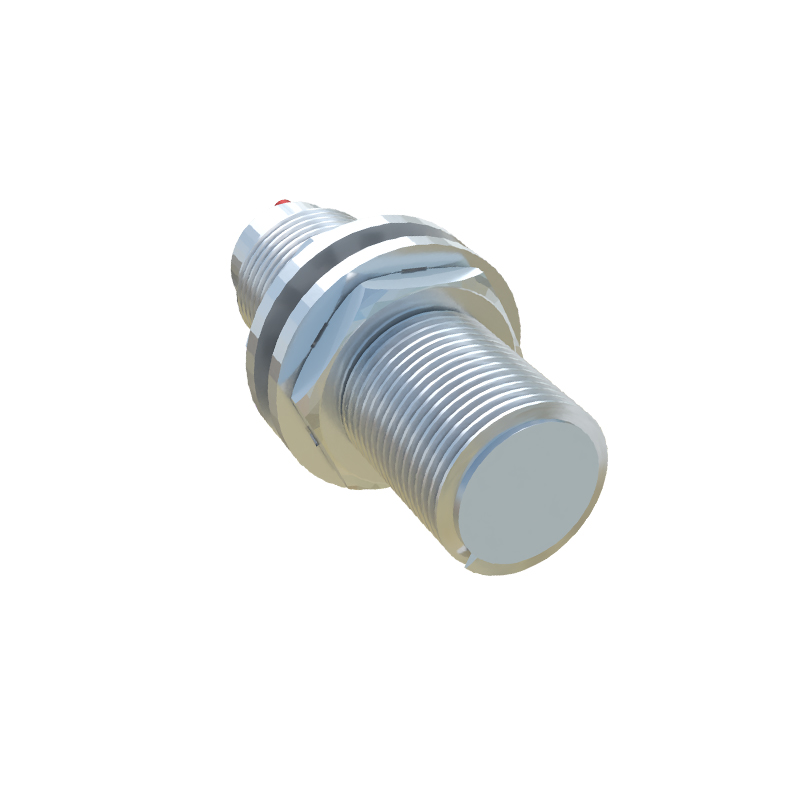
Power Supply Connections: Red and Blue Wires
Correct connection of the power supply wires is the foundation of sensor operation. The red wire must be connected to the positive DC voltage source. It is crucial to verify the sensor's rated voltage, commonly 12-24 VDC, against the actual supply voltage to prevent damage. The blue wire completes the circuit by connecting to the DC common or ground. A stable and clean power supply is essential; voltage spikes or electrical noise on these lines can cause erratic sensor behavior or premature failure. Engineers should always implement appropriate circuit protection, such as fuses or surge protectors, in the supply lines. Furthermore, ensuring proper grounding through the blue wire is vital for shielding the sensor from electromagnetic interference (EMI) prevalent in industrial environments, thereby guaranteeing stable signal integrity.
The Output Signal: Function of the Black Wire
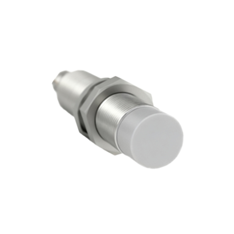
The black wire is the dynamic interface between the sensor and the controlled device, such as a PLC input, relay, or indicator lamp. Its behavior is defined by the sensor's transistor type. In a PNP configuration, the sensor's internal solid-state switch connects the black wire to the positive supply (red wire) when activated. This "sources" current to the load. Conversely, in an NPN configuration, the black wire is connected to the ground (blue wire) upon activation, "sinking" current from the load. It is imperative to match the sensor's output type (PNP or NPN) with the input requirements of the controller. Connecting a PNP sensor to an NPN-compatible input, or vice versa, will result in a non-functional circuit. The black wire's state—switched high (PNP) or low (NPN)—directly communicates the detection event to the control system.
Wiring Diagrams and Practical Implementation
A clear wiring diagram is indispensable for correct installation. For a typical PNP sensor connection: The red wire goes to the DC+ terminal, the blue wire to the DC- terminal, and the black wire to the input channel of the PLC. The load (the PLC input) is then connected between the black wire and DC-. For an NPN sensor, the black wire connects to the PLC input, and the load is connected between the DC+ and the black wire. Practically, technicians should use shielded cables in high-noise environments, connecting the shield to ground at only one end to prevent ground loops. Always power down the circuit before making connections. After wiring, perform a functional test by introducing a target metal to the sensor's sensing face and verifying the correct state change at the controller using diagnostic tools.
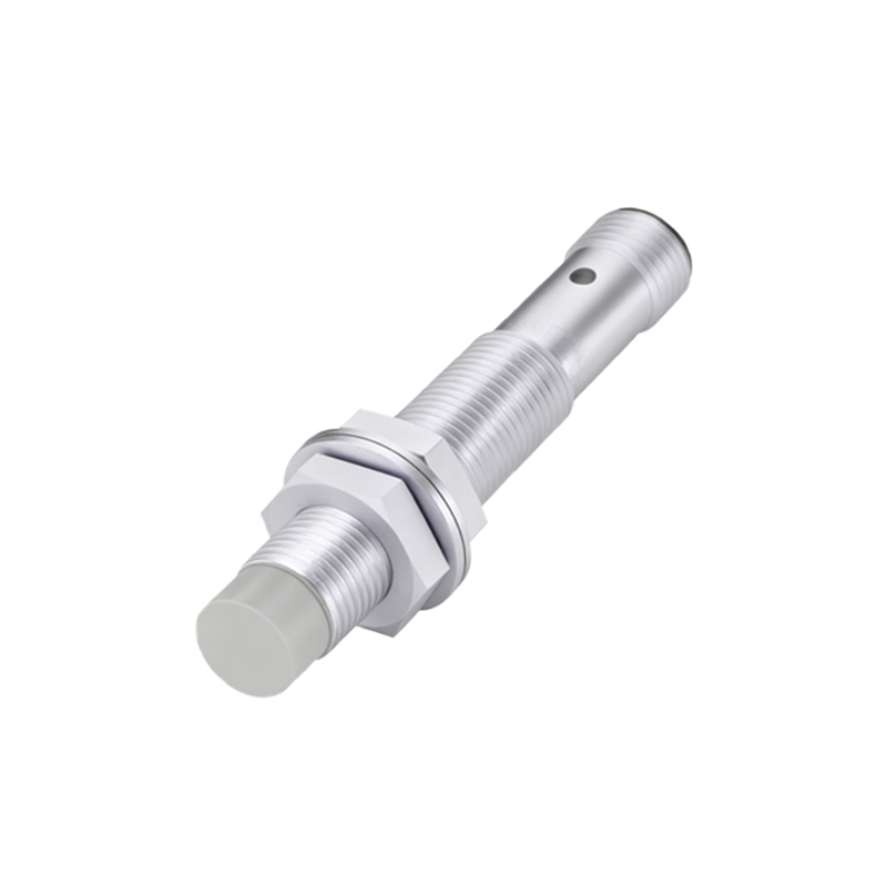
Troubleshooting Common Wiring Issues
Several common problems stem from incorrect wiring of the red, black, and blue leads. If the sensor fails to power on, first check for voltage between the red and blue wires with a multimeter. No voltage