Introduction to Photoelectric Speed Sensing
Photoelectric sensors have become a cornerstone technology for non-contact speed measurement in various industrial and automotive applications. The fundamental principle relies on the modulation of a light beam, typically infrared or laser, by a moving object. A classic setup involves a light source, a photodetector, and a rotating or linearly moving component that interrupts the light path. The sensor generates a series of electrical pulses corresponding to these interruptions. By accurately measuring the frequency of these pulses and knowing the geometric relationship between the interrupting features (like teeth on a gear or marks on a belt), the rotational or linear speed can be precisely calculated. This method offers significant advantages, including high accuracy, fast response times, and the absence of mechanical wear, making it ideal for demanding environments.
Core Components and Circuit Diagram Overview
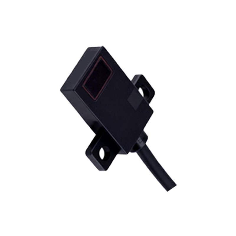
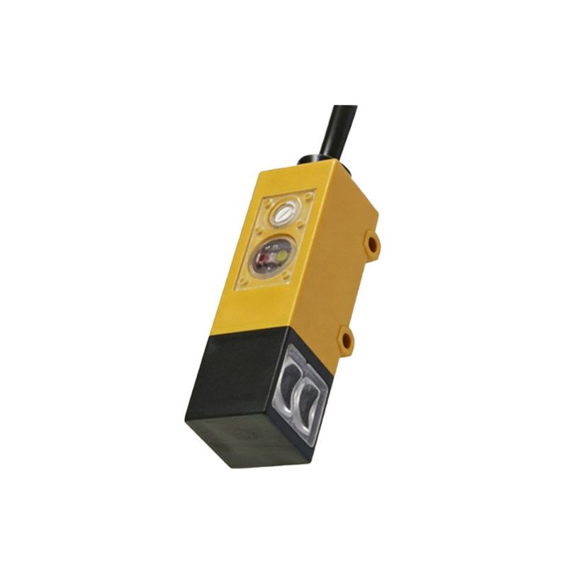
A standard photoelectric speed measurement system comprises several key electronic and optical components. The primary elements include an emitter, often an infrared LED or a laser diode, and a receiver, such as a phototransistor or a photodiode. These are housed in a sensor assembly, sometimes with a slit or lens to focus the beam. The target object, like a slotted disk or a reflective strip, modulates the light. The accompanying electronic circuit typically features a constant current source for the emitter to ensure stable light output. The receiver's output is a weak, noisy analog signal. This signal is fed into a conditioning circuit, which includes amplification stages and a Schmitt trigger to convert the analog pulses into clean, digital square waves suitable for processing by a microcontroller or a dedicated frequency counter.
Signal Conditioning and Pulse Shaping
The raw signal from the photodetector is rarely perfect. It may suffer from low amplitude, background light noise, and slow rise/fall times. Therefore, signal conditioning is critical for reliable measurement. The first stage is usually a transimpedance amplifier, which converts the photodiode's current signal into a usable voltage. Following this, active band-pass filtering is employed to attenuate low-frequency drift and high-frequency electrical noise. The clean analog waveform then enters a comparator circuit, often configured as a Schmitt trigger. The Schmitt trigger provides hysteresis, which prevents multiple output transitions due to signal noise or slight fluctuations when the input voltage is near the threshold. The output is a precise digital pulse train whose frequency is directly proportional to the target's speed.
Speed Calculation Methodology
Once a clean digital pulse train is obtained, speed calculation is straightforward. The system's microcontroller or dedicated hardware timer measures the time period between consecutive pulses or counts the number of pulses within a fixed time window. For a rotating shaft with a single slot or reflective mark, each pulse corresponds to one full revolution. The rotational speed in Revolutions Per Minute (RPM) is calculated as RPM = (60 / (Pulse Period in seconds)). For a multi-toothed gear with 'N' teeth, the formula becomes RPM = (60 * Frequency in Hz) / N. For linear speed measurement, if the target has marks spaced at a known distance 'd', the linear velocity v = d * f, where 'f' is the measured pulse frequency. Advanced systems use interpolation techniques for higher resolution.
Practical Implementation and Wiring Diagram
A practical implementation involves careful physical and electrical design. The wiring diagram connects the sensor assembly to a control unit. The emitter is powered through a current-limiting resistor from a regulated voltage supply (e.g., 5V or 12V). The receiver's collector (for a phototransistor) is typically pulled up to the supply voltage via a resistor, with the signal taken from the collector node. For longer cable runs or electrically noisy environments, using shielded cables and placing the conditioning circuitry close to the sensor is advisable. Many modern integrated photoelectric sensors provide a direct digital (PNP/NPN) or analog (0-10V, 4-20mA) output, simplifying integration into Programmable Logic Controllers (PLCs) or data acquisition systems. The diagram must also include proper grounding to minimize interference.
Advantages, Limitations, and Industry Applications
The photoelectric method offers high precision and resolution, limited only by the number of pulses per revolution and the timer's resolution. It provides a fast dynamic response, crucial for closed-loop control systems. Being non-contact, it eliminates friction and wear. However, limitations exist. The optical path can be obstructed by dust, oil, or fog, requiring regular maintenance or sealed housings. Ambient light, especially from strobes or sunlight, can interfere, necessitating modulated light sources with synchronous detection in critical applications. This technology is ubiquitous, finding use in automotive applications (anti-lock braking systems, engine RPM), industrial automation (conveyor belt speed, motor control), and consumer electronics (computer fan speed control). Understanding the principle diagram is essential for engineers to select, install, and troubleshoot these robust sensing systems effectively.