Introduction to Inductive Proximity Sensors
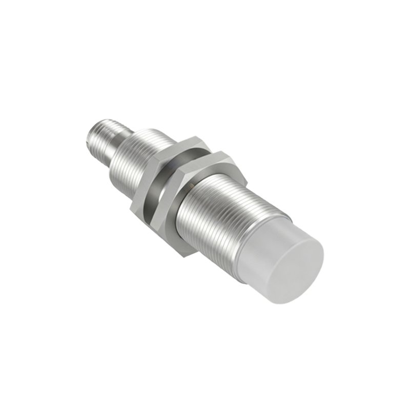
Inductive proximity sensors are fundamental components in industrial automation, widely used for non-contact detection of metallic objects. Operating on the principle of electromagnetic induction, these sensors generate an oscillating electromagnetic field. When a metallic target enters this field, eddy currents are induced, causing a change in the sensor's oscillation amplitude. This change is detected and converted into a switching signal. Their robustness, reliability in harsh environments, and lack of mechanical wear make them indispensable in manufacturing, packaging, and material handling systems. Understanding their electrical behavior, particularly voltage drop, is crucial for ensuring optimal system performance and longevity.
Defining Voltage Drop in Sensor Circuits
Voltage drop refers to the reduction in voltage between the power supply source and the electrical load—in this case, the inductive proximity sensor and its connected controller or PLC input. This drop occurs due to the inherent resistance and impedance within the circuit conductors, connections, and the sensor itself. According to Ohm's Law (V = I × R), the voltage drop (V) is directly proportional to the current (I) flowing through the circuit and the total resistance (R) of the path. In DC sensor circuits, resistance is the primary factor, while in AC circuits, both resistance and inductive reactance contribute. Even a seemingly minor voltage drop can push the operating voltage below the sensor's minimum specified level, leading to erratic behavior or complete failure.
Primary Causes of Excessive Voltage Drop
Several factors can contribute to problematic voltage drops in systems using inductive proximity sensors. Excessive cable length is a predominant cause; longer wires increase circuit resistance, leading to a higher drop. Using cables with an insufficient conductor cross-sectional area (gauge) similarly raises resistance. Poor-quality or corroded connections at terminals, junction boxes, or splices introduce additional resistance points. Environmental factors like high ambient temperature can increase conductor resistance. Furthermore, voltage drop is exacerbated in circuits where multiple sensors or other loads share a common power line, causing cumulative current draw. Lastly, power supplies with inadequate voltage regulation or those operating at the lower limit of the sensor's voltage range are more susceptible to drop-related issues.
Operational Impacts and Failure Symptoms
An undiagnosed or unmitigated voltage drop can manifest in various operational problems that compromise system reliability. The most common symptom is intermittent or "chattering" operation, where the sensor output fluctuates unpredictably as the voltage at the sensor dips below its operational threshold. This can cause false triggers or missed detections in automated processes. In severe cases, the sensor may fail to switch on entirely, appearing completely non-functional. Even when operating, a sensor with insufficient voltage may exhibit a reduced sensing range, failing to detect targets at its specified nominal distance. Over time, operating at low voltage can increase internal stress on the sensor's electronic components, potentially leading to premature failure and increased maintenance costs.
Measurement and Diagnostic Procedures
Accurately diagnosing a voltage drop issue requires systematic measurement. Technicians should use a calibrated digital multimeter to measure the voltage directly at the sensor's power terminals during operation—specifically when the sensor is actively switched on and drawing current. This "under-load" measurement should be compared to the voltage measured at the power supply output. The difference is the total circuit voltage drop. It is critical to verify that the voltage at the sensor remains within its specified operating range (e.g., 10-30 VDC) under all load conditions. Additionally, checking for voltage stability when the sensor switches state is important, as inrush currents can cause momentary dips. Inspecting all physical connections for tightness and signs of corrosion is an essential complementary step.
Effective Mitigation Strategies and Best Practices
Preventing and correcting excessive voltage drop involves both design considerations and corrective actions. First, during system design, calculate the expected voltage drop for the planned cable length and gauge, ensuring the power supply voltage is sufficiently higher than the sensor's minimum requirement to compensate. Using cables with a larger conductor cross-section (lower gauge number) is one of the most effective ways to reduce resistance. For long-distance runs, consider implementing a distributed power system with local power supplies or boosters near sensor clusters. Ensuring all connections are clean, secure, and use proper terminals minimizes contact resistance. In existing installations, relocating the power supply closer to the sensors or installing a dedicated higher-gauge power cable for problematic circuits are common solutions. Regularly monitoring supply voltage as part of preventive maintenance can catch issues before they cause downtime.
Conclusion and Key Takeaways
Voltage drop is a critical, yet often overlooked, electrical characteristic in circuits powering inductive