Understanding Photoelectric Sensor Components
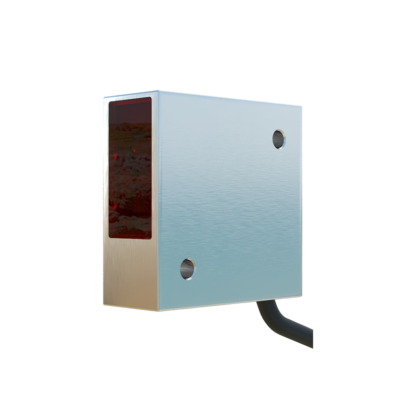
Before beginning the wiring process, it is crucial to identify the key components of a typical photoelectric sensor. The main body houses the emitter (light source) and receiver. It will have a cable outlet or a built-in connector with several wires. Common wire colors include brown, blue, black, and white, though this can vary by manufacturer. The brown wire is typically for the positive DC supply voltage (L+ or V+), and the blue wire is for the common negative or 0V (L- or V-). The black wire is usually the switched output signal, and the white wire may be used for a complementary output or control input. Always consult the specific datasheet for your sensor model. You will also need a DC power supply matching the sensor's voltage rating (e.g., 10-30 VDC) and the load device, such as a programmable logic controller (PLC) input, relay, or indicator lamp.
Pre-Wiring Safety and Preparation
Safety is paramount. Ensure all power sources are locked out and tagged out (LOTO) before handling any wires. Gather the necessary tools: wire strippers, crimping tools, screwdrivers, and the appropriate connectors. Have the sensor's instruction manual and wiring diagram readily available. Plan the sensor's physical mounting location, considering the sensing range, environmental factors like dust or ambient light, and the path for the wiring conduit or cable carrier. Verify that the power supply voltage is compatible and stable. Incorrect voltage can permanently damage the sensor. Prepare the wires by stripping a small portion of the insulation from the ends, taking care not to nick the conductor.
Wiring a Standard 3-Wire DC Sensor (NPN Output)
This configuration is extremely common in industrial automation. First, connect the power supply. Take the brown wire from the sensor and connect it to the positive terminal of your DC power supply (+24V is a common standard). Connect the sensor's blue wire to the negative terminal (0V) of the same power supply. This provides operating power to the sensor's internal circuitry. The sensor's output is on the black wire. For an NPN type sensor, this provides a switching connection to the negative (0V) rail. Connect the black wire to one terminal of your load (e.g., the PLC input module). Connect the other terminal of the load back to the positive supply voltage. When the sensor detects an object, it internally connects the black wire (output) to the blue wire (0V), completing the circuit and activating the load.
Wiring a Standard 3-Wire DC Sensor (PNP Output)
The PNP configuration is another prevalent standard. The power connections remain identical: brown to +V, blue to 0V. The difference lies in the output function. For a PNP sensor, the black output wire provides a switching connection to the positive voltage rail. Connect the sensor's black wire to one terminal of your load. Connect the other terminal of the load to the 0V (negative) of the power supply. When the sensor is activated, it internally connects the black wire to the brown wire (+V), sourcing current to the load and thus activating it. It is critical not to mix NPN and PNP wiring with incompatible load circuits, as this will prevent operation.
Connecting to a PLC Digital Input Module
Integrating the sensor with a PLC is a typical application. For a PNP sensor connected to a sinking PLC input: Connect the sensor's black wire to the PLC input point (e.g., I0.0). The common terminal of that PLC input group must be connected to 0V. When the sensor activates, it sends +24V to the PLC input, registering a logic HIGH. For an NPN sensor connected to a sourcing PLC input: Connect the sensor's black wire to the PLC input point. The common terminal of that PLC input group must be connected to +24V. When activated, the NPN sensor connects the input to 0V, registering a logic LOW. Always check your PLC module's specifications to determine if it requires sinking (PNP) or sourcing (NPN) signals.
Wiring a 4-Wire Sensor with Dual Outputs
Some sensors offer two independent outputs, often one Normally Open (NO) and one Normally Closed (NC), or complementary NPN and PNP outputs. These will have an additional wire, commonly white or gray. The standard brown (+V) and blue (0V) power connections are made first. The black wire might be the NPN output or the NO output, and the white wire could be the PNP output or the NC output. For example, to use both a NO (black) and NC (white) output, wire each to separate loads. The NO load circuit will be active when an object is detected, while the NC load circuit will be active when no object is present and will turn off upon detection. Carefully follow the manufacturer's pinout diagram to avoid errors.
Testing and Troubleshooting the Circuit
After all connections are secure, apply power. Most photoelectric sensors have a built-in LED status indicator. A steady green or yellow light often indicates power is present. When the sensing beam is unobstructed, the output LED (usually orange or red) may be on or off depending on the sensor's light-on/dark-on mode. Pass a target object through the sensing beam. Observe the output LED; it should change state. Use a multimeter to verify voltage at the sensor terminals: approximately 24V between brown and blue. Check the output voltage between the black wire and blue wire (for NPN) or brown wire (for PNP) while triggering the sensor. If the sensor fails to operate, re-check all wiring against the diagram, verify power supply voltage, and ensure the sensing mode (light operate or dark operate) is correctly configured via any DIP switches on the sensor body.