Displacement laser sensors are essential tools in precision measurement and automation, offering high accuracy for distance, thickness, and position detection. Proper wiring is critical to ensure reliable operation and prevent damage. This guide provides a clear, step-by-step approach to connecting these sensors, covering common types and practical tips.
Most displacement laser sensors have a standard set of terminals, typically including power supply, output signals, and communication interfaces. The first step is to identify the sensor's specifications from its datasheet or label. Common voltage ratings are 12-24 VDC, though some models support wider ranges. Incorrect voltage can lead to malfunction or permanent failure.
Begin by preparing the cables. Use shielded cables to minimize electrical noise interference, which is crucial for maintaining signal integrity in industrial environments. Strip the wire ends appropriately and, if applicable, attach connectors as per the sensor's design. For sensors with screw terminals, ensure the wires are securely fastened without loose strands that could cause short circuits.

The basic wiring configuration involves three main connections: power, ground, and output. Connect the positive wire (often brown or red) from your power supply to the sensor's V+ or Vin terminal. Connect the negative wire (blue or black) to the GND or 0V terminal. Double-check polarity, as reversing it can damage the sensor. Some sensors include a protective fuse or reverse-polarity protection, but it's best not to rely on this.
Output signals vary by sensor type. Analog outputs (e.g., 0-10V or 4-20mA) are common for continuous distance measurement. For a voltage output, connect the analog output wire to your controller's analog input. For current output, a precision resistor may be needed to convert the signal. Digital outputs (e.g., NPN/PNP open-collector) are used for switching applications. An NPN output sinks current to ground when active, while a PNP sources current. Connect the output wire to the appropriate input module on your PLC or controller, ensuring compatibility with the sensor's output type.
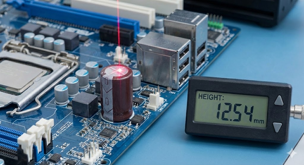
Many advanced sensors feature serial communication interfaces like RS-485, Ethernet/IP, or IO-Link for data transmission and configuration. For RS-485 wiring, use twisted-pair cables and connect the A and B lines correctly, often with termination resistors at the network ends to prevent signal reflections. Always follow the manufacturer's pinout diagram precisely.
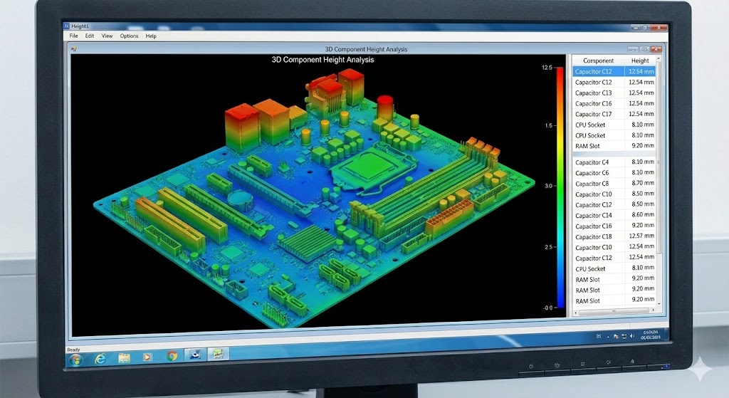
After wiring, perform a systematic check. Inspect all connections for tightness and correct placement. Power on the system gradually, monitoring for unusual heat or sounds. Use a multimeter to verify voltage levels at the sensor terminals. Test the output by placing a target at known distances and checking the readout on your display or software.
Common pitfalls include using unshielded cables in noisy environments, neglecting proper grounding, or overloading the output circuit. Ensure the sensor's housing is grounded if specified, and keep power cables separate from signal lines to avoid crosstalk. For long cable runs, consider voltage drop and use thicker gauges if necessary.
In summary, wiring a displacement laser sensor requires attention to electrical details and adherence to manufacturer guidelines. Correct installation not only guarantees accuracy but also extends the sensor's lifespan. Always consult the specific sensor manual for unique requirements, as designs can vary between models and brands. With careful planning and execution, these sensors will provide stable, high-precision performance in your measurement systems.