Introduction to XY Wiring Photoelectric Sensors
In the realm of industrial automation and machinery control, photoelectric sensors stand as critical components for non-contact detection, positioning, and measurement. Among the various configurations and wiring schemes, the XY wiring method for photoelectric sensors represents a specific and often utilized approach in complex control systems. This method fundamentally relates to how the sensor is integrated into a circuit, typically involving the definition of the X and Y terminals for power supply and output signal connections. Unlike simpler two-wire sensors, XY wiring provides distinct paths for power input and signal output, enhancing reliability and simplifying troubleshooting in demanding industrial environments such as packaging lines, material handling systems, and automated assembly stations.
Core Principles and Electrical Configuration
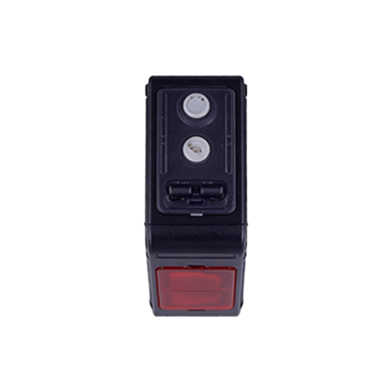
The term "XY wiring" typically refers to a three-wire DC sensor configuration. In this standard setup, the X wire (often brown) is connected to the positive DC supply voltage (V+), the Y wire (often blue) is connected to the common negative or 0V (V-), and the third wire (often black, white, or gray) serves as the output signal line. This clear separation of power and output circuits is the hallmark of XY wiring. The sensor's internal electronics, including the emitter (LED or laser diode) and the receiver (phototransistor or photodiode), are powered through the X and Y lines. The output circuit, which is optically isolated or uses a solid-state switch like a transistor, then switches the signal line relative to either V+ or V- depending on whether it is a sourcing (PNP) or sinking (NPN) output. This design minimizes electrical interference and allows for direct interfacing with programmable logic controllers (PLCs), counters, and other control devices.
Key Advantages in Industrial Applications
The XY wiring scheme offers several tangible benefits that justify its widespread adoption. First and foremost is electrical stability. By providing a dedicated and stable power supply through separate X and Y wires, the sensor's performance is less susceptible to voltage drops or noise that might be present on the load circuit. Secondly, it simplifies installation and maintenance. Technicians can quickly identify and test the power circuit (X-Y) independently of the output signal. Furthermore, the availability of both NPN (sinking) and PNP (sourcing) output types in XY-wired sensors provides flexibility for integration with different PLC input card types, a crucial factor in global manufacturing where electrical standards vary. This wiring method also typically supports faster switching speeds and longer sensing distances compared to two-wire alternatives, making it ideal for high-speed production lines.
Selection Criteria and Installation Best Practices
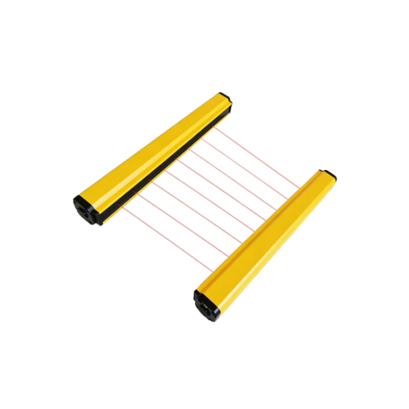
Selecting the correct XY-wired photoelectric sensor requires careful consideration of several parameters. The operating voltage range (commonly 10-30V DC) must match the available control voltage. The output type (NPN or PNP) must be compatible with the controller's input module. The sensing mode—diffuse (proximity), retro-reflective, or through-beam—is chosen based on the required range, target material, and environmental conditions. During installation, it is imperative to follow the manufacturer's datasheet for wire color coding. Proper shielding and routing of cables away from high-voltage power lines are essential to prevent electromagnetic interference. Secure connections using crimp ferrules and strain relief at the cable gland will prevent wire breakage due to vibration, a common issue in mechanical environments. Always ensure the load (e.g., the PLC input) is protected with a flyback diode for inductive loads or a surge suppressor.
Common Troubleshooting Techniques
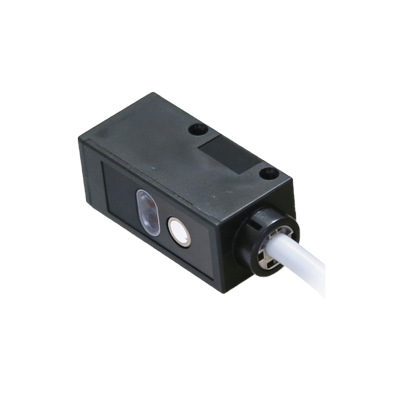
When an XY-wired photoelectric sensor malfunctions, a systematic approach is key. Begin by verifying the power supply across the X and Y wires with a multimeter; absence of correct voltage points to a power source or wiring issue. Next, check the output signal. With the sensor powered and a target present, measure the voltage between the signal wire and the Y wire (for PNP) or X wire (for NPN). A change in state indicates proper sensing. If power is correct but no output signal change occurs, inspect the sensing head for obstruction, misalignment, or contamination from dust or oil. Environmental factors like ambient light, heavy spray, or extreme temperatures can also cause failure. Consulting the sensor's indicator LED (most have a power/status LED and a separate output activation LED) provides immediate visual diagnostic clues.
Future Trends and Integration
The evolution of XY wiring photoelectric sensors continues alongside Industry 4.0. Modern iterations now incorporate advanced functionalities while maintaining the robust XY electrical interface. These include IO-Link communication capability, which adds a digital data channel on top of the standard switched signal, enabling parameter setting, condition monitoring, and diagnostic data reporting. Furthermore, sensors are becoming more ruggedized with higher IP ratings (e.g., IP67, IP69K) for harsh washdown environments. The fundamental XY wiring principle remains a reliable backbone, ensuring that these smarter sensors can be seamlessly retrofitted into existing infrastructure while providing enhanced data for predictive maintenance and overall equipment effectiveness (OEE) calculations, bridging traditional robust wiring with modern digital factory concepts.