Understanding Infrared Proximity Sensor Components
Infrared proximity sensors are widely used in automation, robotics, and safety systems for non-contact object detection. A typical sensor consists of an IR emitter, a photodiode or phototransistor receiver, signal conditioning circuitry, and output interface. The emitter transmits infrared light, which reflects off objects within range. The receiver detects the reflected signal, and the internal circuitry processes it to determine proximity. Key electrical components include power pins (VCC and GND), output pins (digital or analog), and sometimes adjustment potentiometers for sensitivity or range calibration. Understanding these elements is crucial before examining wiring configurations, as incorrect connections can lead to malfunction or damage.
Standard Wiring Diagram and Pin Configuration
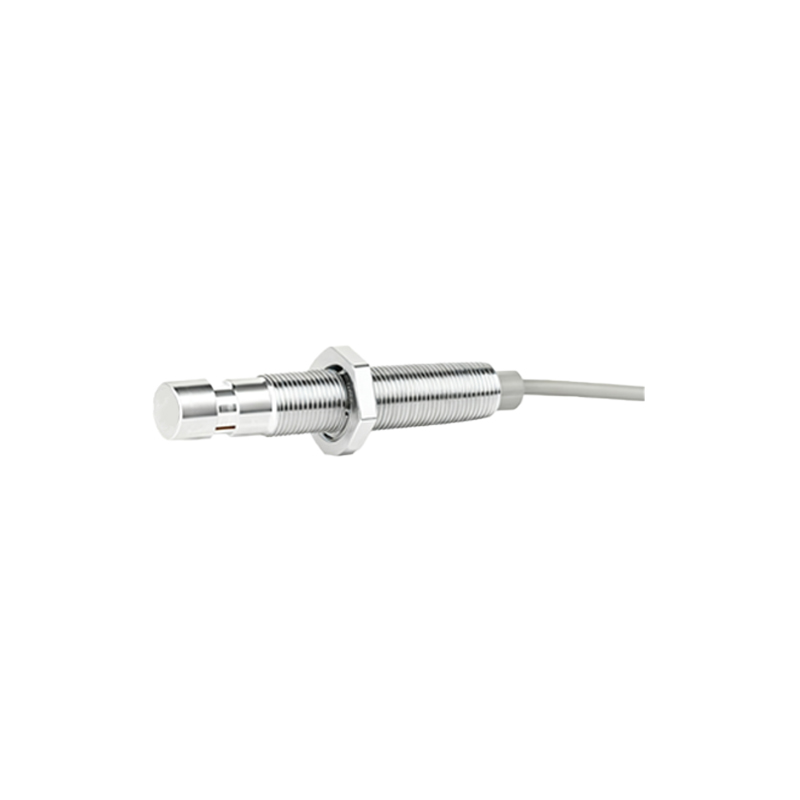
Most IR proximity sensors follow a common three-wire or four-wire design. For a basic three-wire sensor (e.g., common models like E18-D80NK or Sharp GP2Y0A21), the pins are VCC (typically 3.3V to 5V DC), GND (ground), and OUT (signal output). Connect VCC to the positive supply of your controller (like Arduino or PLC), GND to the common ground, and OUT to a digital or analog input pin for reading data. Four-wire sensors may include additional pins for enable/disable functions or separate emitter/receiver control. Always refer to the datasheet for voltage tolerances—exceeding them can destroy the sensor. Use a multimeter to verify connections if unsure.
Connecting to Microcontrollers (Arduino Example)
To interface with an Arduino, start by powering the sensor from the 5V pin and linking GND to Arduino GND. Connect the OUT pin to a digital pin (e.g., D2) for digital sensors or an analog pin (e.g., A0) for analog variants. For digital types, the output is HIGH/LOW based on detection; use digitalRead() in code. Analog sensors output variable voltage proportional to distance—read with analogRead() and map values to distance units. Include a pull-down resistor if needed to prevent floating signals. Example code: initialize serial communication, set pin modes, and loop to read/output proximity data. Ensure stable power by avoiding long wires that cause voltage drops.
Integration with PLCs and Industrial Systems
In industrial setups, IR sensors often connect to Programmable Logic Controllers (PLCs) via discrete or analog input modules. For discrete connections, wire the sensor output to a PLC input card, with power sourced from the PLC’s DC supply or external 24V DC (common in industry). Analog sensors require analog input modules to process 0-10V or 4-20mA signals. Use shielded cables to reduce electrical noise in high-interference environments. Configure PLC programming (e.g., ladder logic) to monitor sensor status and trigger actions like stopping conveyors. Always adhere to ISO safety standards, implementing emergency stop circuits independently of sensor outputs.
Power Supply Considerations and Noise Reduction
Reliable operation depends on clean, stable power. Use regulated DC power supplies matching sensor specifications (e.g., 5V±0.25V). Avoid sharing power lines with motors or inductive loads to prevent voltage spikes—add separate regulators or filters if necessary. For noise immunity, place decoupling capacitors (e.g., 100nF ceramic) near sensor VCC/GND pins and use twisted-pair or shielded cables. In sensitive applications, opt for sensors with built-in noise rejection or modulated IR signals to ignore ambient light. Test under real conditions: fluorescent lights or sunlight can cause false triggers, so adjust sensitivity potentiometers or housing positions accordingly.
Troubleshooting Common Connection Issues
If the sensor fails, first check wiring with a continuity tester. Incorrect polarity (reversing VCC/GND) may permanently damage components. Measure output voltage: digital sensors should swing between 0V and VCC; analog outputs should vary smoothly with object distance. Erratic readings often stem from power instability—verify supply voltage under load. For intermittent detection, inspect for obstructions, dirty lenses, or misaligned emitters/receivers. Update controller code to debounce signals or average analog readings. Consult datasheets for LED indicators: many sensors have status LEDs that blink during detection, aiding diagnostics. Replace faulty units if internal circuitry is compromised.
Advanced Applications and Daisy-Chaining
For multi-sensor systems, such as robotic navigation or assembly lines, daisy-chaining multiple IR sensors saves wiring and controller inputs. Connect all VCC and GND lines in parallel to a robust power source,