Introduction to Proximity Sensor Fundamentals
Proximity sensors are indispensable components in modern industrial automation, providing non-contact detection of objects. Among the various types, inductive proximity sensors are widely used for detecting metallic targets. Their operation hinges on the principle of electromagnetic induction. A high-frequency oscillating circuit generates an electromagnetic field from the sensor's active face. When a metallic object enters this field, eddy currents are induced on the target's surface. These eddy currents draw energy from the oscillator, causing a reduction in the oscillation amplitude. This change is detected by a threshold circuit, which subsequently triggers a change in the sensor's output state. The core distinction in wiring and signal interpretation lies in the output configuration, categorized primarily as NPN or PNP sourcing.
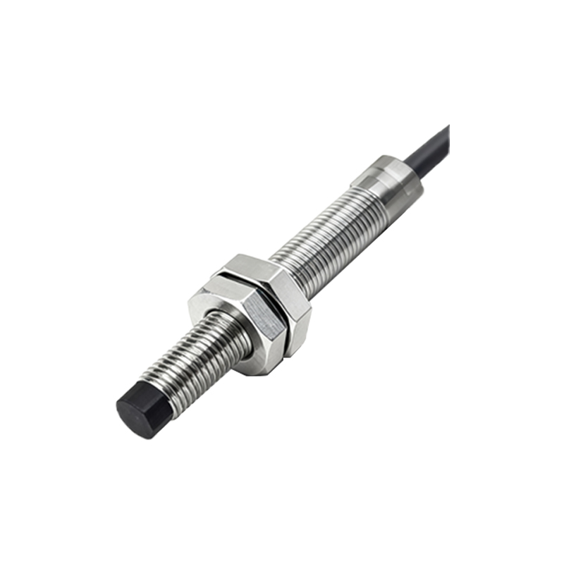
Delving into NPN Transistor Output Operation
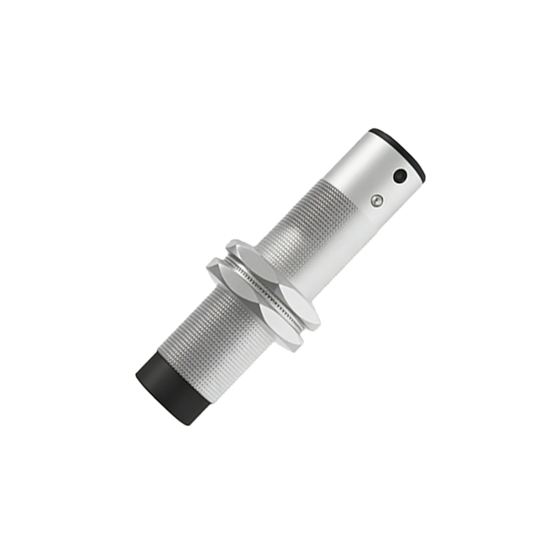
An NPN output sensor utilizes an NPN bipolar transistor as its switching element. In this configuration, the transistor is positioned between the load and the ground (common negative). When the sensor is inactive (no target detected), the transistor is in an 'off' state, presenting a high impedance. No current flows from the output terminal to the ground. Upon detecting a target, the sensor's internal circuit switches the NPN transistor 'on'. This action effectively connects the output terminal to the ground (0V), allowing current to sink from the load, through the output wire, and into the sensor to ground. Therefore, an NPN sensor is often described as a 'sinking' sensor. The load, such as a PLC input module, must be connected between the positive supply voltage and the sensor's output wire. The sensor acts as a switch to ground, completing the circuit when activated.
Exploring PNP Transistor Output Operation
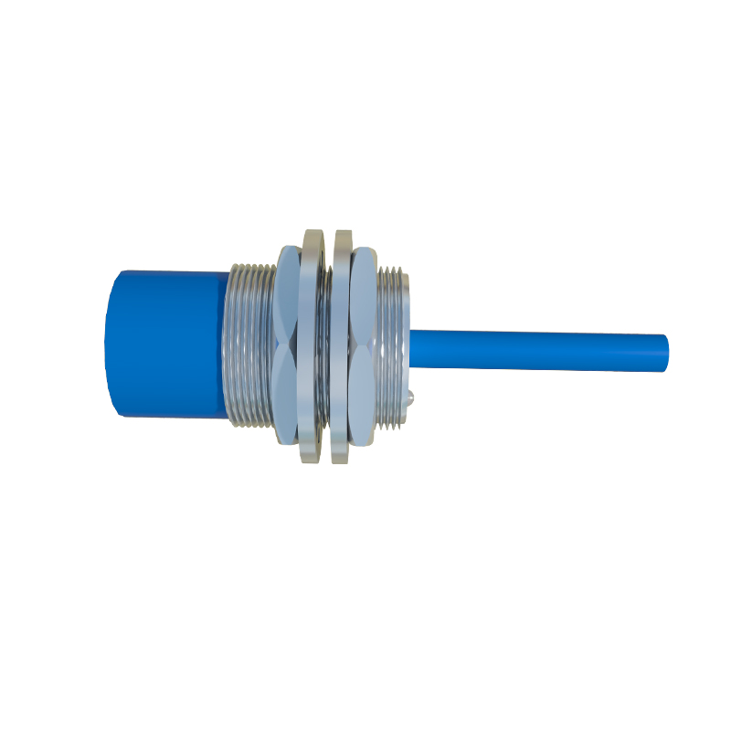
Conversely, a PNP output sensor employs a PNP bipolar transistor. Here, the transistor is situated between the positive supply voltage and the load. In the inactive state, the transistor is 'off', and the output terminal is disconnected from the positive supply. When a target is detected, the internal circuit turns the PNP transistor 'on'. This connects the output terminal directly to the positive supply voltage, sourcing current to the load. Thus, a PNP sensor is termed a 'sourcing' sensor. The load is connected between the sensor's output wire and the ground. The activated sensor provides the positive voltage to drive the load, with current flowing from the sensor, through the load, and to ground.
Wiring Diagrams and Practical Circuit Implementation
Visualizing the wiring is crucial for correct installation. For a typical DC sensor, three wires are standard: brown (positive +V), blue (common 0V or negative), and black (output signal). In an NPN sensor circuit, the brown wire connects to the positive DC supply. The blue wire connects to the supply negative (ground). The black output wire connects to one side of the load (e.g., a PLC digital input). The other side of that load must then be connected back to the positive supply. When the NPN sensor activates, it sinks current, pulling the load's input towards ground potential. For a PNP sensor, the brown and blue wires are connected identically. However, the black output wire connects to one side of the load, and the other side of the load is connected to the supply negative (ground). Activation sources positive voltage to the load.
Key Differences and Selection Criteria
The primary difference is the direction of current flow and the resulting voltage state of the output signal when active. An active NPN output is at a low voltage (near 0V, sinking), while an active PNP output is at a high voltage (near +V, sourcing). Selection often depends on the control system's input card design. Many PLCs in Europe and Asia are designed to work with PNP (sourcing) inputs, where the common terminal of the input card is connected to ground. In contrast, NPN (sinking) sensors are traditionally more common in Japan and in some North American applications, where the PLC input common is often connected to the positive voltage. Understanding the existing control logic—whether it requires a 'high' or 'low' signal to indicate a true condition—is paramount. Incorrect pairing can lead to non-operation or potential damage.
Application Considerations and Industry Best Practices
Beyond the basic electrical configuration, several factors influence sensor choice. The operating voltage range (commonly 10-30V DC), sensing distance, target material, switching frequency, and environmental ratings (IP67, etc.) are critical. For wiring in complex systems, consistency is key. Using all PNP or all NPN sensors within a subsystem simplifies design and troubleshooting