Introduction to Photoelectric Sensor Identification
Identifying the correct model number of a photoelectric sensor is a fundamental task for engineers, technicians, and procurement specialists in industrial automation. These sensors are critical components in countless applications, from packaging and material handling to automotive assembly and safety systems. Each sensor model possesses unique specifications regarding sensing range, light source, output type, housing material, and electrical connections. Using an incorrect or incompatible sensor can lead to system failures, production downtime, and safety hazards. This guide provides a systematic, industry-standard approach to locating and interpreting the model number on a photoelectric sensor, ensuring accurate replacement, integration, and troubleshooting.
Primary Locations of the Model Number
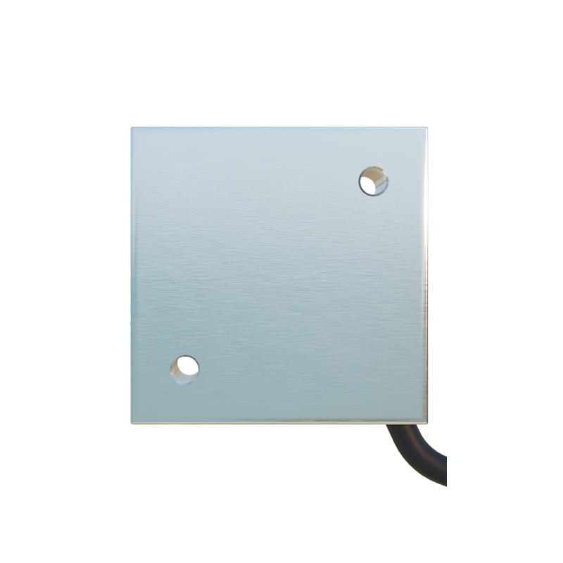
The model number is typically engraved, printed, or labeled on the sensor body itself. The most common location is on the side of the sensor housing. For cylindrical sensors, check the barrel; for rectangular or block-style sensors, inspect the larger flat surfaces. Often, the information is presented on a durable nameplate or label that includes not only the model number but also key electrical ratings, certifications (like CE or UL), and a serial number. In some compact designs, the information may be laser-etched directly onto the housing material. Always ensure the area is clean and well-lit to read the often small and finely printed characters. If the label is worn, using a magnifying glass or digital microscope can be helpful.
Deciphering the Model Number Code
A photoelectric sensor model number is not a random string; it is an alphanumeric code that encapsulates its core features. While formats vary by manufacturer, they generally follow a logical sequence. The prefix often indicates the sensor family or series (e.g., "E3Z" for Omron, "BOS" for Banner, "WL" for SICK). Following characters usually specify the sensing mode: "T" for through-beam, "R" for retro-reflective, "D" for diffuse (proximity). Subsequent digits and letters denote critical parameters: sensing distance (e.g., "2M" for 2 meters), light source type ("L" for red LED, "G" for green LED, "L" for laser), output configuration (NPN/PNP, NO/NC), housing shape and size, and connection type (cable, connector). Consulting the manufacturer's datasheet or product catalog is essential to decode the specific nomenclature.
Utilizing Manufacturer Documentation and Websites
When the printed label is illegible or only a partial number is visible, manufacturer resources are invaluable. Start by visiting the official website of the suspected manufacturer. Most leading brands, such as Keyence, Panasonic, Allen-Bradley, and Schneider Electric, offer robust online product selectors and search functions. Enter any known portions of the model number into the search bar. Alternatively, use the website's parametric search tools to filter by observed physical characteristics (shape, size, connector) and electrical specifications. Downloading the official datasheet for a potential match allows for a direct comparison of dimensions, drawings, and performance curves with the physical unit in hand.
Cross-Referencing Based on Physical and Electrical Characteristics
If the model number is completely unreadable, identification becomes a process of technical deduction. Carefully document all observable features. Measure the housing dimensions and thread size precisely. Note the color and type of the lens. Identify the connection method: does it have a fixed cable, a quick-disconnect (M8, M12), or a terminal block? Using a multimeter, safely determine the output type (NPN sinking or PNP sourcing) and state (normally open or normally closed) by simulating a sensing condition. The light source color (red, green, blue, infrared) is a key differentiator. The sensing range can be roughly tested in a controlled environment. Compiling this dossier of specifications will dramatically narrow down the possibilities in any product catalog.
Leveraging Distributor and Industry Expertise
Industrial automation distributors and technical sales representatives are excellent resources. They handle products from multiple manufacturers daily and possess practical, hands-on experience. Contact a reputable distributor with clear photos of the sensor from multiple angles, detailed measurements, and any legible fragments of text. Their internal cross-reference databases can often identify equivalent or replacement models. Furthermore, online industry forums and communities, such as those on PLCs.net or specific manufacturer user groups, host collective knowledge where experienced engineers may recognize a sensor from an image or description.
Importance of Accurate Model Identification
Correct model identification is paramount for operational integrity. It ensures the replacement sensor matches the required voltage range (10-30V DC, 20-250V AC), output current capacity, and switching speed. It guarantees the mechanical form factor will fit the existing mounting bracket and that the sensing characteristics (range, beam pattern, response time) are compatible with the application. Misidentification can cause electrical incompatibility, damaging the sensor or the controller (PLC). It can also lead to unreliable detection, creating jams, miscounts, or unsafe conditions in machinery. Taking the time to identify the model correctly is a investment in system reliability and safety.
Best Practices for Future Reference
To avoid this challenge in the future, implement proactive asset management. Upon installation, create a detailed inventory log that records the sensor model number, serial number, location in the machine, and the date of installation. Attach a durable, weather-resistant tag with the model number near the sensor if possible. Maintain well-organized digital or physical files of all product datasheets and manuals for the equipment. When purchasing spare parts, buy at least one extra sensor and store it with its documentation. This practice minimizes downtime during critical failures and streamlines the maintenance process, ensuring long-term efficiency and cost-effectiveness in plant operations.