Introduction to Fiber Optic Photoelectric Sensors
Fiber optic photoelectric sensors are advanced devices used for detecting the presence, absence, or position of objects without physical contact. They operate by transmitting light through optical fibers to a sensing head, where changes in light intensity are measured to determine object characteristics. These sensors are highly valued in industrial automation for their precision, immunity to electromagnetic interference, and ability to function in harsh environments. The installation process is critical to ensure optimal performance, and a clear diagram can guide engineers in proper setup. This article provides a detailed overview of the installation steps, supported by a simplified diagram, to help professionals implement these sensors effectively in various applications, such as manufacturing lines, robotics, and quality control systems.
Components and Tools Required
Before beginning the installation, gather all necessary components and tools. Key parts include the fiber optic sensor unit (comprising an amplifier and fiber cable), mounting brackets, connectors, and power supply cables. The fiber cable typically consists of a transmitter and receiver pair, which may be separate or combined in a single unit depending on the sensor type. Essential tools involve screwdrivers, wrenches, a multimeter for electrical checks, and cable ties for organization. Additionally, ensure you have the manufacturer's manual for specific guidelines. A well-prepared setup reduces installation time and minimizes errors, leading to reliable sensor operation. It's also advisable to inspect components for damage before proceeding to avoid malfunctions.
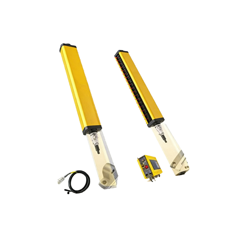
Step-by-Step Installation Procedure
Start by mounting the sensor amplifier in a secure location, preferably on a DIN rail or panel, using the provided brackets. Ensure the area is free from excessive vibration, heat, or moisture to prevent damage. Next, connect the fiber optic cable to the amplifier, aligning the connectors carefully to avoid bending or stressing the fibers. Route the cable away from power lines and moving machinery to reduce interference and physical wear. Attach the sensing head at the desired detection point, securing it with mounts that allow for adjustable positioning. Use the diagram to verify correct orientation—for example, in through-beam sensors, align the transmitter and receiver directly opposite each other. Finally, connect the power supply and output cables according to the wiring diagram, typically involving DC voltage inputs and relay outputs for signal transmission.
Wiring and Electrical Connections
Proper wiring is crucial for sensor functionality and safety. Refer to the installation diagram to identify terminals for power, ground, and output signals. Most fiber optic sensors operate on low-voltage DC power (e.g., 12-24V DC), so use appropriately rated cables and ensure polarity is correct to prevent damage. Connect the ground wire to a stable earth point to reduce noise and enhance stability. For output connections, link the sensor to control systems like PLCs or relays, following color-coding standards (e.g., brown for positive, blue for negative, black for output). Test connections with a multimeter to confirm voltage levels and continuity before powering on. This step minimizes electrical faults and ensures seamless integration into automated processes.
Alignment and Calibration Techniques
After physical installation, align the sensing head precisely for accurate detection. Use alignment tools or visual indicators, such as LED lights on the sensor, to adjust the position until the beam is optimally focused on the target. For reflective sensors, ensure the surface is within the specified range and angle. Calibration involves setting sensitivity thresholds via the amplifier's controls, such as potentiometers or digital interfaces, to distinguish between objects and background noise. Follow the diagram to adjust settings like response time and light intensity, and perform test runs with sample objects to verify detection consistency. Regular recalibration may be needed in dynamic environments to maintain performance over time.
Troubleshooting Common Issues
Even with careful installation, issues can arise. Common problems include false triggers, no detection, or unstable signals. Refer to the diagram to check for misalignment, dirty fiber ends, or loose connections. Clean optical surfaces with recommended solvents and realign components if necessary. Electrical issues might stem from incorrect wiring or power fluctuations—use a multimeter to diagnose and rectify these. Additionally, environmental factors like ambient light or temperature extremes can affect performance; consider using shielded cables or protective housings as per the diagram guidelines. Consulting the manufacturer's troubleshooting section can provide specific solutions for persistent errors.
Maintenance and Best Practices
To ensure long-term reliability, implement a maintenance routine based on the installation diagram. Regularly inspect fiber cables for wear, cracks, or bending beyond the minimum radius, and replace damaged parts promptly. Keep sensing heads clean from dust and debris, and verify alignment periodically, especially in high-vibration areas. Document any adjustments made during calibration for future reference. Best practices include using cable management systems to organize wires, labeling connections for easy identification, and training personnel on proper handling procedures. Adhering to these guidelines extends sensor lifespan and reduces downtime in industrial operations.
Conclusion and Applications
In summary, a clear installation diagram simplifies the setup of fiber optic photoelectric sensors, enhancing their effectiveness in diverse applications. From automotive assembly to packaging lines, these sensors offer non-contact detection with high accuracy. By following the steps outlined—from component preparation to calibration—engineers can achieve optimal performance and minimize errors. Always prioritize safety and manufacturer recommendations during installation. As technology advances, these sensors continue to evolve, supporting smarter automation and improved efficiency in modern industries.