Understanding Key Selection Criteria
Choosing the right proximity sensor for an application is critical for reliable operation. The first consideration is the sensing technology itself. Inductive sensors are ideal for detecting metallic objects, while capacitive sensors can detect a wider range of materials, including liquids and non-metals. Photoelectric sensors offer the longest sensing ranges and are excellent for detecting small objects. Ultrasonic sensors excel in harsh environments and can measure distance. The target material, size, and required sensing distance directly dictate the suitable technology. Environmental factors are equally important. One must assess the operating temperature range, potential exposure to chemicals, oils, or coolants, and the presence of dust or washdown requirements. Sensors with high IP (Ingress Protection) ratings, such as IP67 or IP69K, are necessary for demanding industrial settings.
Electrical Specifications and Output Configuration
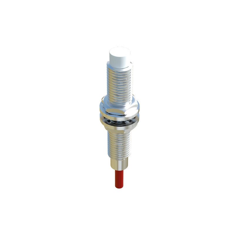
Matching the sensor's electrical characteristics to the control system is a fundamental step. The operating voltage must be compatible, with common DC versions being 10-30V DC and AC versions often 90-250V AC. The output type is a key decision point. Two-wire sensors are simple to wire but have a residual current when off. Three-wire sensors (PNP or NNP sourcing) and four-wire sensors (with both PNP and NPN outputs) offer more control and are standard in programmable logic controller (PLC) systems. The output current rating must be sufficient to drive the connected load, such as a relay, PLC input, or indicator lamp. For analog sensors, the output signal range (e.g., 4-20mA, 0-10V) and its linearity relative to the sensing parameter must be confirmed.
Mechanical Design and Mounting Considerations
The physical form factor and installation method significantly impact performance. Cylindrical sensors are common and come in standardized thread sizes like M8, M12, M18, and M30. Rectangular or block-style sensors offer flexibility in tight spaces. The mounting style—flush, non-flush, or factor—affects the sensing range. Flush-mounted inductive sensors can be installed metal-to-metal but have a reduced range. Non-flush versions offer longer ranges but require a clearance zone around the sensing face. Proper alignment between the sensor and the target is crucial; angular misalignment can drastically reduce the effective sensing distance. Vibration-resistant designs and the use of mounting brackets may be necessary in applications with significant mechanical stress.
Wiring Practices and Electrical Noise Immunity
Correct wiring is essential for avoiding malfunctions and ensuring longevity. Always follow the manufacturer's wiring diagram. For DC sensors, observe correct polarity to prevent damage. Shielded cables are recommended for long cable runs or in electrically noisy environments to prevent electromagnetic interference (EMI). The cable gland or connector must provide a proper seal if environmental protection is required. To enhance noise immunity, keep sensor cables separate from high-voltage power lines and motor leads. Using ferrite cores on cables near noise sources can suppress high-frequency interference. For sensors in AC circuits, incorporating a surge suppressor across inductive loads (like solenoids or contactors) protects the sensor's output transistor from voltage spikes.
Calibration, Adjustment, and Setup Procedures
Many modern proximity sensors feature adjustable sensing ranges or sensitivity potentiometers. After installation, fine-tuning may be required. For a standard on/off sensor, the sensitivity should be adjusted so that the sensor reliably detects the target at the required distance without being triggered by background objects or environmental conditions like humidity (for capacitive sensors). Teach-in functions on intelligent sensors allow for easy programming of switch points. For analog sensors, scaling the output to the desired engineering units within the controller is a critical setup step. It is good practice to verify the sensor's operation across the entire range of expected target conditions, including temperature extremes.
Common Failure Modes and Diagnostic Steps
Even robust sensors can fail. Common symptoms include no output signal, intermittent operation, or shortened sensing range. A systematic diagnostic approach begins with checking the power supply voltage at the sensor terminals under load. Verify the load is functional and within the sensor's specifications. Inspect the sensor face for buildup of dirt, metal shavings, or other contaminants that can attenuate the sensing field. For inductive sensors, check if a different metal type has been introduced. Diagnose wiring for loose connections, shorts, or damaged cables. Using a multimeter to check the output state can isolate whether the issue is with the sensor or the downstream circuit. Many sensors have a built-in LED status indicator that provides immediate visual feedback on power and output state.
Preventive Maintenance and Best Practices
Proactive maintenance maximizes sensor