Understanding the Proximity Sensor M5 and Its Common Faults
Proximity sensors, particularly the M5 series, are integral components in modern industrial automation, known for their compact size and reliable non-contact detection capabilities. These inductive sensors are designed to detect metallic objects without physical contact, making them ideal for harsh environments where durability is paramount. The M5 designation often refers to the sensor's threaded barrel size of 5mm. Common faults in M5 proximity sensors typically manifest as intermittent operation, complete failure to detect targets, or erratic output signals. These issues can stem from various sources, including electrical overload, mechanical damage, environmental contamination, or internal component degradation. Understanding the sensor's operating principle—where an electromagnetic field is disturbed by a metallic target, triggering a switch—is crucial for effective troubleshooting. Early fault detection is vital to prevent costly production downtime and maintain system integrity in automated assembly lines, packaging machinery, and robotic systems.
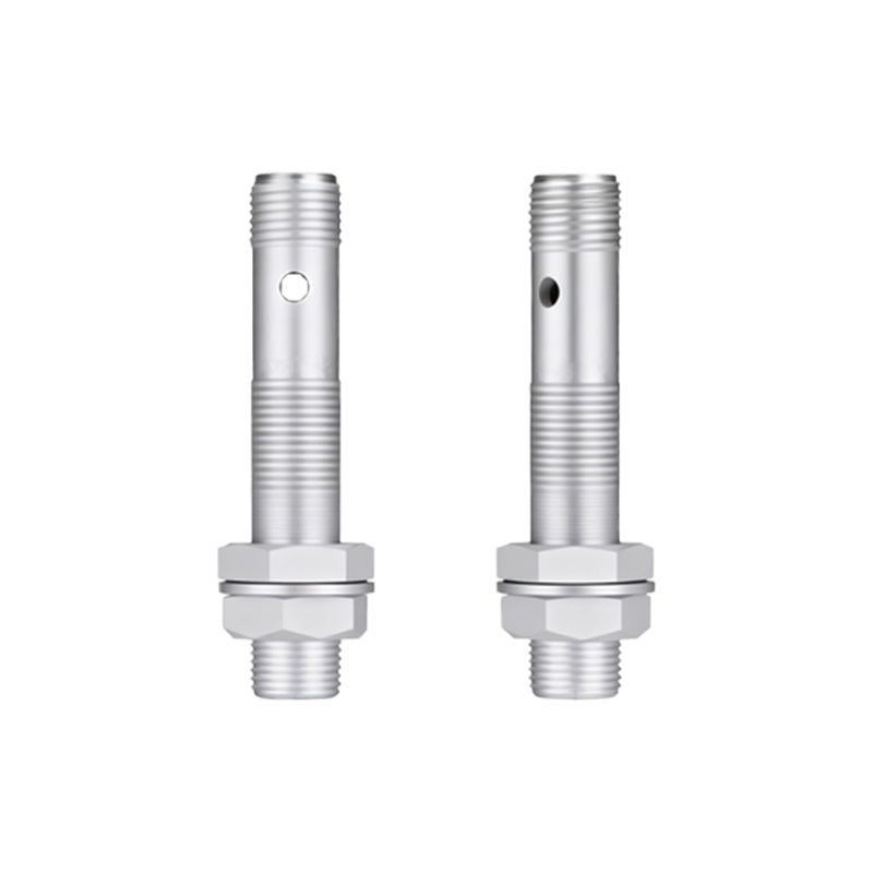
Primary Symptoms and Diagnostic Indicators of M5 Sensor Failure
Identifying a failing M5 proximity sensor requires careful observation of specific symptoms. A frequent initial indicator is inconsistent detection, where the sensor intermittently fails to recognize a target at its specified sensing range. This may be accompanied by an unstable output signal, visible on a multimeter or oscilloscope as voltage fluctuations. In some cases, the sensor's LED indicator (if equipped) may behave erratically, flickering or remaining lit/off contrary to normal operation. Complete non-responsiveness, where the sensor provides no output regardless of target presence, often points to severe internal damage or power supply issues. Another critical symptom is reduced sensing range; a sensor that once detected objects at 2mm may only function at 1mm, indicating internal coil or oscillator circuit degradation. Diagnostic tools such as a digital multimeter for checking supply voltage and output continuity, or an oscilloscope for analyzing signal integrity, are essential for confirming these symptoms before proceeding with physical inspection or replacement.
Step-by-Step Electrical and Mechanical Troubleshooting Procedures
Systematic troubleshooting begins with verifying the electrical connections and power supply. Ensure the sensor is receiving the correct voltage (e.g., 10-30V DC for many M5 models) and that polarity is properly observed. Measure voltage at the sensor's terminals under load to rule out voltage drops from wiring issues. Next, inspect the output load; an excessive current draw beyond the sensor's rating (often around 200mA) can damage the output transistor. Electrically isolate the sensor and test its output with a known-good load, such as a pilot lamp or relay coil within specifications. Mechanically, examine the sensor's face for accumulation of metal shavings, dirt, or coolant, which can attenuate the electromagnetic field. Check for physical damage like dents or cracks in the housing, which may compromise internal seals against liquids and contaminants. Verify the installation: ensure the sensor is not over-tightened, causing housing distortion, and that there is adequate clearance from surrounding metal structures to prevent false triggering or shielding effects.
Environmental Factors and Installation Errors Leading to Faults
The operating environment is a predominant contributor to M5 sensor failures. Exposure to excessive vibration can loosen internal solder joints or damage the ferrite core. High ambient temperatures, often above the sensor's rated specification (e.g., 70°C), can degrade electronic components and insulation. Conversely, in washdown or outdoor applications, moisture ingress or condensation can short circuit the oscillator or amplifier circuitry. Chemical exposure from oils, solvents, or acidic fumes may corrode the housing or epoxy-encapsulated coil. Installation errors are equally critical. A common mistake is mounting multiple M5 sensors in close proximity without adequate lateral spacing, causing mutual interference where one sensor's field influences another. Incorrect target material selection is another pitfall; while inductive sensors detect metals, different materials like stainless steel have a reduced sensing range compared to mild steel, potentially leading to perceived faults if not accounted for in the design phase. Ensuring proper shielding and grounding in electrically noisy environments is also essential to prevent electromagnetic interference from distorting the sensor's signal.
Repair, Replacement, and Preventive Maintenance Strategies
Upon confirming a fault, the decision to repair or replace depends on the sensor's design. Most sealed M5 units are not user-serviceable and require replacement. When installing a new sensor, meticulously follow manufacturer specifications for voltage, wiring, sensing distance, and mounting. For critical applications, consider installing a sensor with enhanced features like overload protection, wider temperature tolerance, or increased resistance to specific chemicals. Implementing a preventive maintenance schedule can drastically reduce unexpected failures. This includes regular visual inspections for contamination or damage, periodic functional checks using a test target at the