Introduction to Photoelectric Sensors in Mahjong Machines
Photoelectric sensors are critical components in modern automatic mahjong machines, ensuring precise tile detection, shuffling, and game flow. These sensors operate by emitting a light beam, typically infrared, and detecting its reflection or interruption. Their strategic placement within the machine's mechanism is paramount for reliable operation. A comprehensive location diagram is not just a technical reference; it is essential for troubleshooting, maintenance, and understanding the machine's automated logic. This article provides a detailed overview of the typical photoelectric sensor positions within a standard automatic mahjong table, explaining the function of each location.

Primary Sensor Locations and Their Functions
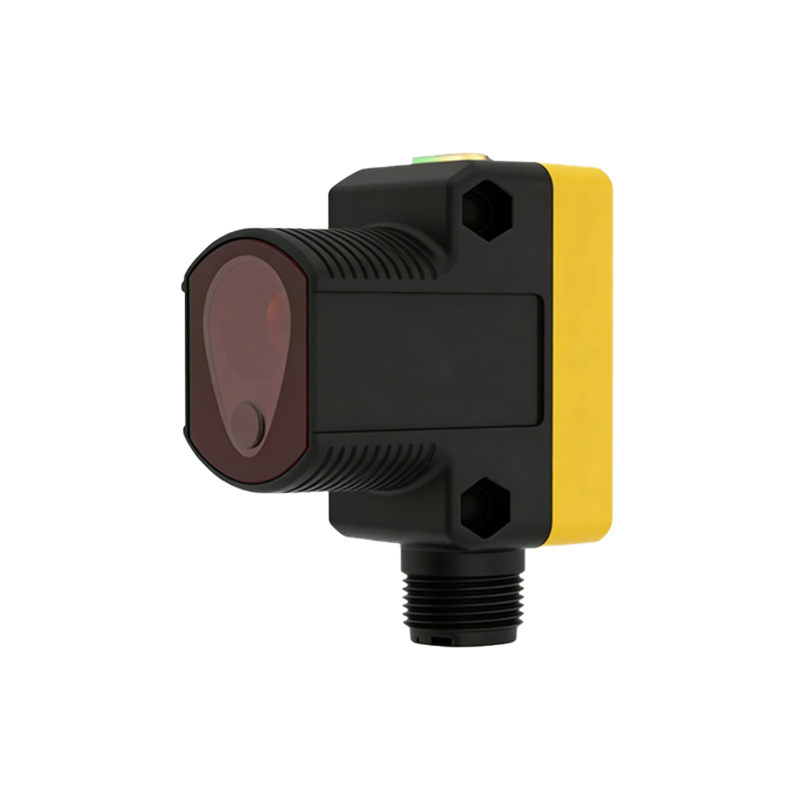
The sensor network in a mahjong machine can be divided into several key zones. First, the Tile Feeding and Elevator Area houses sensors that monitor the tile reservoir and the elevator mechanism. A sensor here confirms when the tile elevator is in the home or "ready" position and detects the presence of tiles ready to be lifted. Another critical set is located in the Shuffling and Distribution Track. Sensors along the circular track count tiles as they pass, ensuring the correct number (usually 14 per player) is delivered to each rack. They also detect jams or misaligned tiles that could disrupt the game.
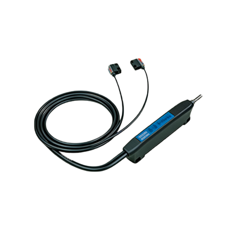
Central Game Area and Wall Building Sensors
Following distribution, tiles are arranged into the "wall." Sensors in this Wall Building and Pushing Mechanism verify the completion of each wall segment. They ensure tiles are properly aligned before the break is made to determine the starting point. Furthermore, sensors are integrated into the Dice Roller and Game Start Module. They detect the roll of the electronic dice and signal the machine to reveal the wall break and commence dealing. This area is crucial for initiating the automated sequence accurately.
Player Rack and Discard Area Monitoring
The Player Rack Area contains sensors that may confirm a tile has been properly taken by a player or indicate when a rack is empty, signaling the end of a round. More prominently, the Discard Tile Chute employs multiple sensors. These detect when a discarded tile enters the chute, its orientation, and its passage to the central collection area. This monitoring is vital for game integrity, preventing confusion in tile tracking and ensuring smooth recycling of discarded tiles back into the system.
Diagnostic and Safety Sensor Placements
Beyond core gameplay, sensors serve diagnostic and safety roles. Door and Cover Interlock Sensors are safety features that halt machine operation if the cover is opened during a game. Motor and Gear Position Sensors provide feedback on the status of various drive motors, such as those for the shuffling arms or elevator, helping the control board prevent mechanical overloads or mis-timing. Understanding the location of these sensors is key for advanced troubleshooting.
Interpreting a Photoelectric Sensor Location Diagram
A standard location diagram is a schematic overlay on a machine's blueprint. Each sensor is represented by a standardized symbol (often a diode-like icon with an arrow) labeled with a code like "PS1," "PS2," etc., corresponding to a parts list. The diagram shows the sensor's physical mounting point, its beam path, and the target object it monitors (e.g., a gear tooth, tile edge, or flag on an arm). Arrows indicate the direction of infrared emission and reception. Technicians use this map to visually trace sensor circuits during fault finding.
Common Issues and Troubleshooting via Location
Knowledge of sensor locations streamlines repair. A common error like "Tile Jam" often points to sensors in the distribution track. If the machine fails to build the wall, the wall alignment sensors are the first check. Intermittent operation might be caused by dust or debris on the lens of a sensor in the discard chute. By consulting the location diagram, a technician can quickly isolate the problematic zone, check for physical obstructions, clean the lenses, or test the sensor's electrical output with a multimeter, rather than conducting a time-consuming full inspection.
Importance for Maintenance and Repair
Regular maintenance using the sensor location diagram as a guide can prevent failures. This involves periodic cleaning of sensor lenses to ensure unimpeded light transmission, checking for loose wiring connectors at each sensor mount, and verifying that mechanical parts have not shifted and broken the sensor's alignment. For repair professionals, this diagram is indispensable. It allows for precise ordering of replacement parts by location code and ensures correct reinstallation, maintaining the machine's original calibration and timing.
Conclusion and Technical Resource Value
In summary, the photoelectric sensor location diagram is the nervous system map of an automatic mahjong machine. From tile feeding to discard processing, each sensor plays a specific role in the automated sequence. For operators, service technicians, and enthusiasts, mastering this layout is fundamental to ensuring optimal machine performance, quick diagnostics, and effective repairs. It transforms a complex electromechanical system into a logical, serviceable array of components, upholding the reliability and enjoyment of the game.