Fundamental Operating Principle
Inductive magnetic proximity sensors are non-contact electronic devices designed to detect the presence or absence of ferromagnetic objects, such as iron and steel, within a defined sensing range. Their operation is grounded in electromagnetic induction. At the core of the sensor lies a coil wound around a ferrite core, which forms part of an oscillator circuit. When energized, this coil generates a high-frequency alternating electromagnetic field that emanates from the active face of the sensor. In the absence of a target, the oscillator operates at its base frequency. When a ferromagnetic object enters this dynamic field, eddy currents are induced on the surface of the target. These currents draw energy from the oscillator, causing a measurable change in its amplitude or frequency. This change is detected by a subsequent evaluation circuit, which triggers a solid-state switching output, typically in the form of a PNP, NPN, or analog signal. It is crucial to note that these sensors specifically react to magnetic materials; non-ferrous metals like aluminum or copper generally fall outside their standard detection capabilities unless specially designed versions are used.
Key Components and Design Variations
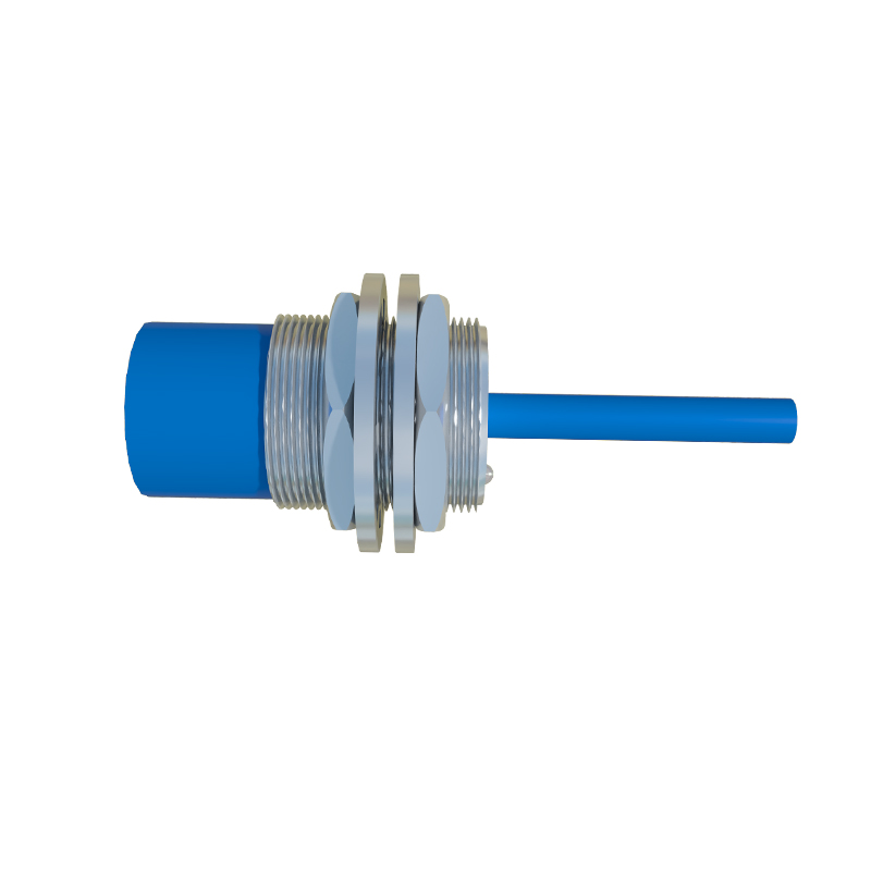
The performance and application suitability of an inductive magnetic proximity sensor are dictated by its internal design and housing. The sensing coil and ferrite core are the primary transducers. They are encapsulated within a robust housing, often made of nickel-plated brass, stainless steel, or high-grade plastics like PBT, to withstand industrial environments involving dust, moisture, and mechanical impact. Key design variations include shielded (flush-mountable) and unshielded (non-flush) versions. Shielded sensors have a metallic ring surrounding the sensing face, which confines the magnetic field, allowing them to be installed flush with metal mounting surfaces without false triggering. Unshielded sensors offer a longer sensing range but require a non-metallic zone around them during installation. Furthermore, sensors are available in diverse form factors—tubular, rectangular, or ring-shaped—and with various output configurations (e.g., NO/NC, push-pull, IO-Link) and connection types (cable or connector).
Primary Advantages in Industrial Settings
The widespread adoption of inductive magnetic proximity sensors in automation stems from several compelling advantages. Their non-contact nature ensures wear-free operation, leading to exceptional longevity and reliability, even in high-cycle applications like counting or position verification on production lines. They are inherently robust, capable of operating in harsh conditions with exposure to oil, coolants, and vibration. Unlike optical sensors, they are virtually immune to ambient light, dust, fog, or dirt accumulation on the sensing face, making them ideal for dirty or washdown environments. They offer high switching frequencies, enabling detection of very fast-moving objects. Additionally, their solid-state design provides fast response times and bounce-free switching signals, which is critical for precise control logic in Programmable Logic Controllers (PLCs).
Typical Application Scenarios
These sensors are ubiquitous across manufacturing and process industries. Common applications include end-position detection of cylinders in pneumatic systems, where a sensor detects the piston's ferromagnetic ring. They are extensively used for rotational speed monitoring by detecting gear teeth or bolts on a rotating shaft. In material handling, they verify the presence of metal parts on conveyors, act as limit switches on automated guided vehicles (AGVs), or control sorting gates. Machine tools employ them for tool position detection, spindle orientation, and chuck jaw monitoring. Their reliability also makes them suitable for safety-related functions, such as verifying guard door closure, though this requires devices specifically designed and certified for safety applications (e.g., with redundant outputs).
Critical Selection Criteria
Selecting the correct sensor requires careful analysis of several parameters. The nominal sensing distance (Sn), specified for a standard mild steel target, is the primary consideration. A safety factor (typically 0.8) is applied to Sn to account for temperature fluctuations and supply voltage tolerances, defining the reliable operating distance. The target material, size, and shape must be considered; smaller targets or those made of different steel grades may require a reduction factor. The sensor's housing material and IP (Ingress Protection) rating must match the environmental conditions (e.g., IP67 for temporary immersion). Electrical characteristics are vital: the operating voltage range (commonly 10-30V DC), output type (sourcing/sinking), and current capacity must be compatible with the control system. For advanced diagnostics and parameterization, sensors with IO-Link digital communication are increasingly preferred.
Installation and Maintenance Best Practices
Proper installation is paramount for reliable operation. For shielded sensors, ensure the mounting material is non-ferrous if installed in a recess. Maintain the specified lateral and