Understanding the Core Operating Principle
The first step in deciphering any proximity sensor specification sheet is to fundamentally understand its operating principle. Specifications differ dramatically between inductive, capacitive, ultrasonic, and photoelectric sensors. An inductive sensor, for instance, detects metallic objects, and its key specs will revolve around target material (ferrous/non-ferrous) and switching frequency. A capacitive sensor reacts to both metallic and non-metallic materials, with specifications heavily emphasizing dielectric constant and sensitivity adjustment. Always identify the technology (e.g., "Inductive, shielded") before proceeding, as this frames all subsequent parameters.
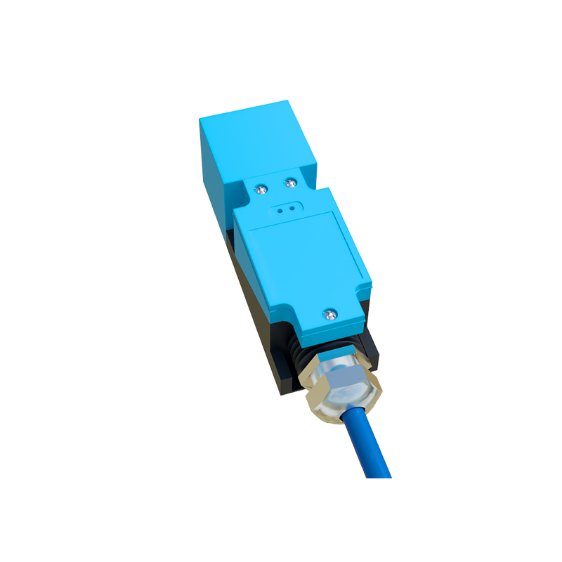
Decoding Sensing Distance and Tolerance
The rated sensing distance (Sn) is arguably the most critical parameter. This nominal value, often 5mm, 10mm, or 20mm, is defined for a standard target. However, engineers must scrutinize the associated tolerances and conditions. Specifications list operational tolerances (e.g., ±10%) due to manufacturing variances and temperature influences. More importantly, the effective sensing distance (Sr) in real application is reduced. Always check for reduction factors for non-standard targets (e.g., stainless steel vs. mild steel for inductive sensors). The specification will also define the assured operating distance (Sa), which is a guaranteed trigger range under all rated conditions, typically 0 to 81% of Sn.
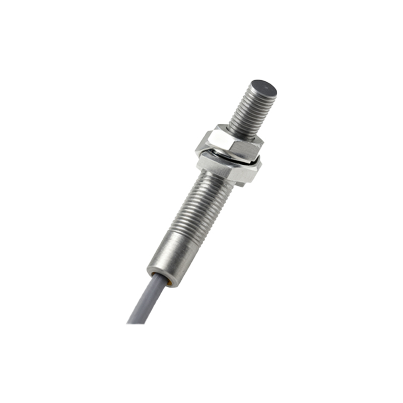
Analyzing Electrical Characteristics and Output Type
This section dictates how the sensor integrates into your control system. First, identify the output configuration: PNP (sourcing) or NNP (sinking), and the output type: normally open (NO) or normally closed (NC). The load current rating is vital—exceeding it can damage the sensor. Key electrical specs include operating voltage range (e.g., 10-30V DC), residual current (Io) when "off," and leakage current when "on." For AC sensors, inrush current handling is crucial. Also, note the short-circuit and reverse polarity protection ratings, which speak to the sensor's robustness in harsh electrical environments.
Evaluating Performance: Switching Frequency and Hysteresis
For dynamic applications, switching frequency (in Hz) determines how fast the sensor can detect objects passing by. A 1kHz sensor can theoretically detect 1000 objects per second. However, real-world performance is affected by target size and approach speed. Hysteresis is another essential performance spec, expressed as a percentage of the sensing distance. This is the difference between the switch-on point as the target approaches and the switch-off point as it recedes. It prevents output chatter when a target is at the exact sensing edge. Higher hysteresis improves stability in environments with vibration.
Assessing Environmental Ratings and Housing
The sensor's housing material (e.g., brass, stainless steel, PBT plastic) and ingress protection (IP) rating define its application limits. An IP67 rating guarantees protection against dust ingress and temporary immersion in water. For washdown or outdoor use, IP69K is required. Temperature specifications are given as an operating range and a storage range. Consider the ambient temperature alongside the sensor's own heat generation. Additionally, check for resistance to specific chemicals, oils, or coolants if applicable. For inductive sensors, the flush-mounting capability (shielded vs. unshielded) is a key mechanical spec affecting installation and sensing field shape.
Interpreting Response Time and Repeatability
Do not confuse switching frequency with response time. Response time is the delay between the sensing event and the output signal change, typically in milliseconds. It includes both the on-delay and off-delay. This parameter is critical for high-speed counting or precision positioning. Repeatability (R) is the precision with which the sensor can detect the same target under identical conditions, usually a small percentage of Sn (e.g., ≤ 2%). This indicates the sensor's consistency and long-term stability, impacting the reliability of automated processes.
Connections, Indicators, and Approvals
Finally, examine the practical connection specs: cable type (PVC, PUR), length, or connector style (M8, M12). Built-in LED indicators (power, output status) are invaluable for diagnostics. Regulatory approvals (UL, CSA, CE, ATEX for hazardous areas) are not mere formalities; they certify the sensor meets specific safety and electromagnetic compatibility (EMC) standards. EMC immunity (to RF interference, surge voltages) ensures reliable operation in electrically noisy industrial settings. Always cross-reference these specs with your plant's standards and the specific demands of the installation location.