Introduction to Photoelectric Sensors in Imaging Systems
Photoelectric sensors are fundamental components in modern industrial automation, serving as the "eyes" of a system. These devices operate by emitting a light beam—typically infrared, visible red, or laser—and detecting changes in the received light signal. The core principle involves the interruption, reflection, or modulation of this beam by a target object. In the context of machine vision and automated inspection, photoelectric sensors provide a highly reliable and precise method for detecting the presence, position, or specific features of items on a production line. Their ability to function accurately at high speeds and in varied environmental conditions makes them an ideal choice for triggering critical actions, such as commanding a camera to capture an image at the exact moment a product is in the correct position. This synergy between sensing and imaging is pivotal for ensuring quality control, guiding robotic arms, and enabling traceability in manufacturing processes.
System Configuration and Integration
Integrating a photoelectric sensor with an industrial camera requires careful planning of the system architecture. The typical setup involves a sensor, a camera (often a high-speed or high-resolution model), a programmable logic controller (PLC) or a dedicated vision controller, and appropriate lighting. The sensor is strategically positioned along the conveyor or assembly line to detect the target. Upon detection, it sends a digital signal—often a 24V DC pulse—to the controller. The controller, programmed with the necessary logic, then issues a trigger command to the camera. This command is usually transmitted via a standard interface like GPIO (General Purpose Input/Output), Ethernet (using protocols like GigE Vision or PoE), or a dedicated hardware trigger line. The timing is critical; engineers must account for sensor response time, signal transmission delay, and camera exposure latency to ensure the captured image corresponds precisely to the desired object position. Proper synchronization eliminates motion blur and guarantees that the vision system analyzes the correct field of view.
Selecting the Right Sensor Type
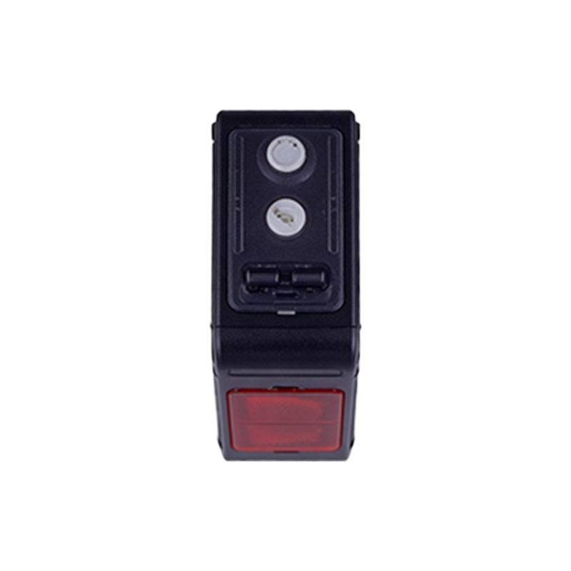
Choosing the appropriate photoelectric sensor is crucial for successful implementation. The main types include through-beam, retro-reflective, diffuse-reflective, and background suppression sensors. Through-beam sensors, with separate emitter and receiver units, offer the longest sensing range and highest reliability, ideal for detecting objects of varying colors and surfaces. Retro-reflective types use a reflector and are suitable for longer ranges than diffuse sensors. Diffuse-reflective sensors detect light reflected directly from the target, making them compact and easy to install but potentially sensitive to the object's color and texture. For triggering cameras in complex backgrounds, background suppression (or foreground sensing) models are invaluable, as they detect objects only within a precise set distance, ignoring anything beyond. Key selection parameters include sensing distance, response time (often in microseconds), light source type, output configuration (NPN/PNP), and environmental ratings (IP67 for dust and water resistance). The sensor must match the line speed, object size, and ambient light conditions of the application.
Optimizing Trigger Timing and Accuracy
Achieving millisecond-precision triggering is the cornerstone of a reliable vision inspection system. The primary challenge is compensating for the physical distance between the sensor detection point and the camera's field of view. Engineers often employ a "trigger offset" or "encoder-based" synchronization method. In a simple setup, the time delay between sensor activation and camera capture is calculated based on conveyor speed and distance. For high-speed lines, using a rotary encoder attached to the conveyor drive provides real-time position data. The PLC or vision controller uses this encoder feedback to issue the camera trigger at the exact position, independent of minor speed fluctuations. Furthermore, setting the sensor's ON/OFF delay functions and the camera's trigger activation mode (like "rising edge" or "falling edge") ensures clean, bounce-free signals. Anti-vibration mounting and shielding from electrical noise are also essential to prevent false triggers that could lead to missed captures or erroneous data.
Application Examples in Industry
The combination of photoelectric sensors and camera triggering is ubiquitous across manufacturing. In automotive assembly, a through-beam sensor detects a car body arriving at a station, triggering a camera to capture images of weld seams for robotic guidance or quality audit. In pharmaceutical packaging, a diffuse sensor with background suppression identifies individual blister packs on a high-speed line, synchronizing a camera to verify pill count and print quality. In logistics, retro-reflective sensors detect parcels on a sorting belt, initiating barcode or label imaging for automated routing. Food and beverage producers use this technology for fill-level inspection, cap alignment checks, and label placement verification. Each application demands a tailored approach to sensor placement, lighting (such as strobe lights synchronized with the camera trigger to freeze motion), and image processing software configuration to analyze the captured images instantly and make pass/fail decisions.
Troubleshooting Common Issues
Even well-designed systems can encounter operational challenges. Common issues include missed triggers, false triggers, and inconsistent image framing. Missed triggers often stem from incorrect sensor alignment, insufficient sensing range for the target, or an object color/material that does not reflect light adequately. Realigning the sensor, adjusting its sensitivity, or switching to a different sensor type (e.g., from diffuse to through-beam) can resolve this. False triggers are frequently caused by ambient light interference (sunlight or factory lighting), reflective backgrounds, or electrical noise from motors. Solutions involve using sensors with modulated light signals, installing light shields or barriers, and employing proper cable shielding and grounding. Inconsistent framing usually points to timing inaccuracies. Recalculating the trigger delay, implementing encoder synchronization, or adjusting the camera's exposure time relative to the line speed typically restores precision. Regular maintenance, including lens and sensor window cleaning, is also vital for sustained performance.
Future Trends and Advancements
The integration of photoelectric sensing and machine vision continues to evolve with Industry 4.0. Smart sensors with integrated IO-Link communication are becoming prevalent, allowing for remote configuration, monitoring, and diagnostics of parameters like signal strength and operating hours directly from the controller. Furthermore, the rise of vision sensors—devices that combine simple imaging and onboard processing with traditional sensor outputs—blurs the line between sensing and inspection. For triggering high-end cameras, Ethernet Advanced Physical Layer (Ethernet-APL) enables faster, more robust communication in hazardous areas. Artificial Intelligence is also making inroads; predictive algorithms can analyze trigger performance data to forecast sensor maintenance needs or automatically adjust timing parameters in response to production changes. These advancements promise even greater reliability, flexibility, and intelligence in automated imaging systems, driving efficiencies in smart factories.