Understanding the 2-Wire Proximity Sensor
A 2-wire proximity sensor is a fundamental component in industrial automation, valued for its simplicity and direct integration into control circuits. Unlike its 3-wire or 4-wire counterparts, it requires only two connection points, typically functioning as both a load and a switch. This design eliminates the need for a separate power supply line, as the sensor draws its operating current directly from the same loop it is controlling. Commonly used for detecting the presence or absence of metallic objects, these sensors are prevalent in applications like machine guarding, counting, and position sensing. Their operation is based on generating an electromagnetic field; when a target enters this field, it causes a change in the sensor's internal oscillation, triggering a switching action. The key advantage lies in reduced wiring complexity and cost, making them a go-to choice for straightforward switching tasks in control panels and machinery.

Basic Operating Principle and Circuit Integration
The core functionality of a 2-wire sensor revolves around acting as a variable impedance device in series with the load. In its normal state (no target detected), a small leakage current, often termed the off-state current or residual current, flows through the sensor to power its internal electronics. This current is typically low enough (usually a few milliamps) to prevent the connected load, such as a PLC input or a relay coil, from activating. When a target is detected, the sensor's internal impedance drops significantly, allowing the full circuit current to flow and thus energizing the load. It is crucial to note that the sensor must be connected in series with the load and the power supply. The load itself is an integral part of the circuit; without it, the sensor cannot complete the current path to function. This series connection is the defining characteristic of 2-wire sensor wiring.
Standard Wiring Procedures and Diagrams
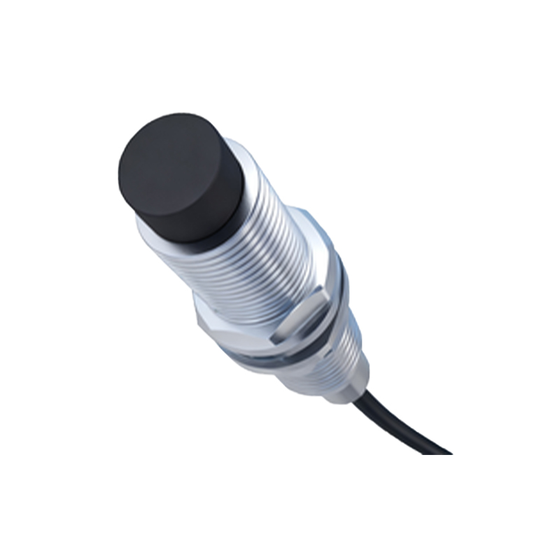
Wiring a 2-wire proximity sensor correctly is essential for reliable operation. The process begins by identifying the sensor's terminals, which are usually labeled as Brown (or +) and Blue (or -), following the common international color-coding standard for AC/DC sensors. For a typical DC circuit, connect the Brown wire to the positive side of the power supply. The Blue wire is then connected to one terminal of the load (e.g., the positive side of a relay coil or a PLC digital input). The other terminal of the load must be connected back to the negative side of the power supply, completing the series loop. For AC circuits, the Brown wire connects to the Line (L) or hot wire, and the Blue wire connects to the load, which then returns to the Neutral (N). Always refer to the manufacturer's datasheet for the specific wiring diagram, as colors and terminal designations can vary. A fundamental rule is to ensure the sensor's voltage rating (e.g., 10-30V DC, 20-250V AC) matches the supply voltage.
Critical Considerations for Load Compatibility
One of the most important aspects of using 2-wire sensors is ensuring load compatibility. The primary challenge is managing the off-state leakage current. If this current is too high for the connected load, it may cause a false activation, such as a relay chattering or a PLC input registering an ON signal when it should be OFF. Conversely, the sensor must provide sufficient on-state current to reliably drive the load when activated. Engineers must verify two key parameters from the sensor datasheet: the maximum leakage current (Ileak) and the minimum operating current (Imin). The connected load's minimum operating current should be greater than the sensor's Ileak, and the sensor's Imin should be less than the load's nominal current draw. For sensitive loads like PLC inputs, an external bleeder resistor (or load resistor) is often wired in parallel to shunt the leakage current and prevent false triggering. Calculating the correct resistor value is vital for system stability.
Troubleshooting Common Installation Issues
Even with correct wiring, issues can arise. Common problems include the load not energizing, intermittent operation, or the load remaining energized when it should be off. First, verify all physical connections are secure and the power supply voltage is within the sensor's specified range. Use a multimeter to check for voltage at the sensor terminals. If the load fails to activate, measure the current in the loop when a target is presented; it should meet or exceed the load's minimum requirement. If the load is falsely ON, measure