Introduction to Photoelectric Sensors
Photoelectric sensors are widely used in industrial automation for detecting the presence, absence, or distance of objects without physical contact. They operate by emitting a light beam—typically infrared, visible red, or laser—and measuring changes in the received light due to reflection, interruption, or transmission. Common types include through-beam, retro-reflective, and diffuse reflective sensors, each suited for specific applications based on range, environmental conditions, and accuracy requirements. Understanding their wiring is crucial for ensuring reliable operation in systems such as conveyor belts, packaging machinery, and safety interlocks. This guide provides a detailed, step-by-step wiring diagram explanation to help engineers and technicians implement these sensors effectively.
Components and Terminology
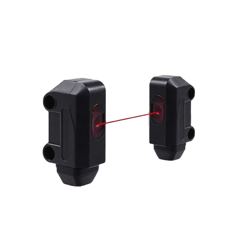
Before diving into wiring, familiarize yourself with key components. A typical photoelectric sensor consists of a light emitter, receiver, housing, and electrical connections. Terminals often include power supply (V+ and V-), output signals (NO/NC contacts or analog outputs), and auxiliary functions like timers or sensitivity adjustments. Wiring diagrams use standard symbols: a circle for the sensor, lines for wires, and labels for voltage (e.g., 12-24V DC) and load (e.g., relay or PLC input). Always refer to the manufacturer's datasheet for specific pinouts, as variations exist between models and brands like Omron, Sick, or Keyence.
Power Supply Connections
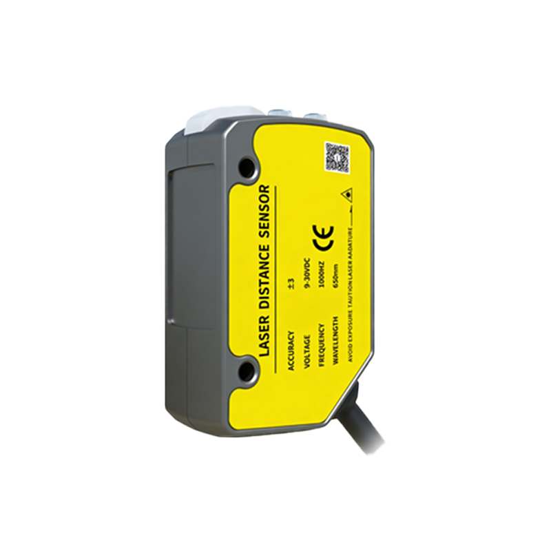
Start by connecting the power supply to ensure the sensor operates correctly. Most industrial photoelectric sensors use DC voltage, commonly 12V or 24V, though AC models are available for high-power applications. Identify the V+ (positive) and V- (negative or ground) terminals on the sensor. Use shielded cables to reduce electrical noise, especially in environments with motors or frequency drives. Connect the V+ wire from the power source to the sensor's V+ terminal, and the V- wire to the V- terminal. Double-check polarity to avoid damage—reverse polarity can fry internal circuits. For safety, install a fuse or circuit breaker in the power line, typically rated slightly above the sensor's current draw (e.g., 100mA).
Output Wiring for Different Loads
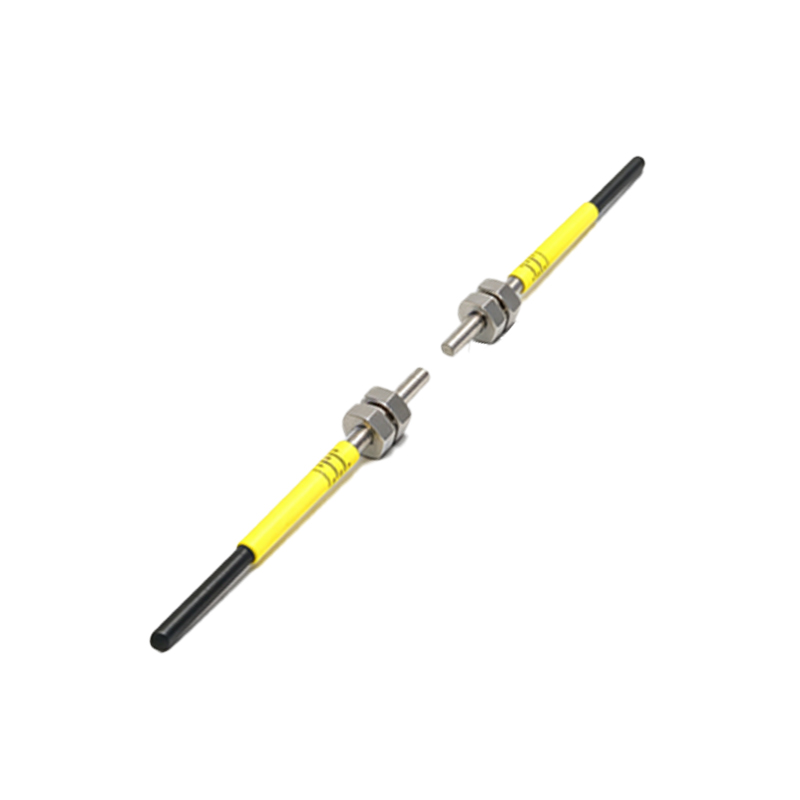
Photoelectric sensors provide outputs to interface with control systems like PLCs, relays, or indicators. Output types include transistor (NPN or PNP) and relay contacts. For NPN (sinking) outputs, the load connects between V+ and the output terminal; when activated, the sensor sinks current to ground. For PNP (sourcing) outputs, connect the load between the output terminal and V-; the sensor sources current from V+. Relay outputs are versatile, handling AC or DC loads directly. In wiring diagrams, show the load—such as a PLC input module or a relay coil—with proper ratings (e.g., max 100mA for transistors). Use color-coded wires: brown for V+, blue for V-, and black for output signals to follow IEC standards.
Wiring Diagrams by Sensor Type
Through-beam sensors have separate emitter and receiver units. Wire the emitter to power only, as it sends a continuous beam. The receiver connects to power and output; when the beam breaks, its output changes state. Retro-reflective sensors combine emitter and receiver in one housing, with a reflector bouncing light back. Wire similarly to through-beam receivers, but ensure the reflector is aligned. Diffuse reflective sensors detect objects by reflecting light off their surface. Their wiring includes sensitivity adjustments via potentiometers or teach-in buttons. Include diagrams with clear labels: for example, "Emitter: Brown to 24V+, Blue to 0V" and "Receiver: Black wire to PLC Input X0." Test with a multimeter to verify voltage levels before full operation.
Shielding and Noise Reduction
Industrial environments often contain electromagnetic interference (EMI) that can cause false triggers or sensor malfunctions. Implement shielding by using twisted-pair or shielded cables for all connections. Ground the shield at one end only—typically at the control panel—to prevent ground loops. Keep sensor wires away from high-voltage lines, motors, and frequency inverters. If using long cables (over 50 meters), consider adding ferrite cores or surge protectors to dampen noise. In diagrams, denote shielded cables with a dashed line around wire groups and specify grounding points. Regular maintenance, like checking insulation and connector integrity, further ensures reliability.
Testing and Troubleshooting
After wiring, perform functional tests. Power up the system and observe the sensor's indicator LED—green for power, yellow or red for output activation. Use a test object to trigger the sensor, verifying the output changes state as expected. If issues arise, check for loose connections, incorrect voltage, or misaligned optics. A multimeter can measure voltage at terminals: V+ to V- should match the supply (e.g., 24V DC), and output voltage should switch between high and low states. Consult the sensor's manual for error codes; for instance, constant LED blinking may indicate overload or short circuit. Document wiring diagrams in system logs for future reference, noting any modifications made during installation.
Safety and Best Practices
Always follow safety protocols when wiring photoelectric sensors. Disconnect power before making connections to avoid electric shock or equipment damage. Use tools with insulated handles and wear appropriate PPE. Adhere to local electrical codes and standards, such as NEC or IEC 60204-1. For hazardous areas, select sensors with proper certifications (e.g., ATEX for explosive atmospheres). In diagrams, include safety elements like emergency stop circuits or protective relays. Regularly inspect wiring for wear, corrosion, or heat damage, especially in harsh conditions like high humidity or vibration. Training personnel on correct wiring procedures minimizes errors and enhances system uptime.
Conclusion and Applications
Proper wiring is fundamental to leveraging photoelectric sensors in automation. They enable precise detection in applications ranging from object counting on production lines to edge detection in robotics. By mastering wiring diagrams—from power links to output configurations—engineers can optimize performance and reduce downtime. Keep diagrams updated with any system changes, and share them across teams for consistency. As technology evolves, smart sensors with IO-Link or Ethernet connectivity offer simplified wiring through digital communication, but core principles remain. Embrace these guidelines to ensure robust, efficient sensor integration in your industrial projects.