Introduction to Sensor Conversion in Concrete Boom Pumps
In the demanding environment of concrete placement, boom pump reliability is paramount. A critical yet vulnerable component in the control system is the linear displacement sensor, often a potentiometric or magnetostrictive device, used to determine the angle and extension of each boom section. These sensors are consistently exposed to harsh conditions: extreme vibration, hydraulic fluid contamination, mechanical shock, and weather. Frequent failures lead to costly downtime, inaccurate positioning, and safety concerns. This article details a robust engineering solution: retrofitting these displacement sensors with non-contact inductive proximity switches. This conversion significantly enhances system durability, simplifies maintenance, and reduces long-term operational costs, offering a practical upgrade for fleet managers and maintenance engineers.
Understanding the Limitations of Traditional Displacement Sensors
Traditional linear displacement sensors provide continuous analog feedback, which is ideal for precise proportional control. However, their mechanical design is their Achilles' heel. Potentiometer-based sensors have a wiper that moves along a resistive element, which wears out over time and is susceptible to ingress of dirt and moisture. Magnetostrictive sensors, while more robust, are complex and expensive to replace. Both types are typically mounted along the boom's movement path, making them prone to physical damage from debris or during maintenance operations. The failure mode often results in erratic boom behavior, complete loss of section control, or persistent fault codes, necessitating immediate attention and replacement—a process that is time-consuming and interrupts critical pouring schedules.
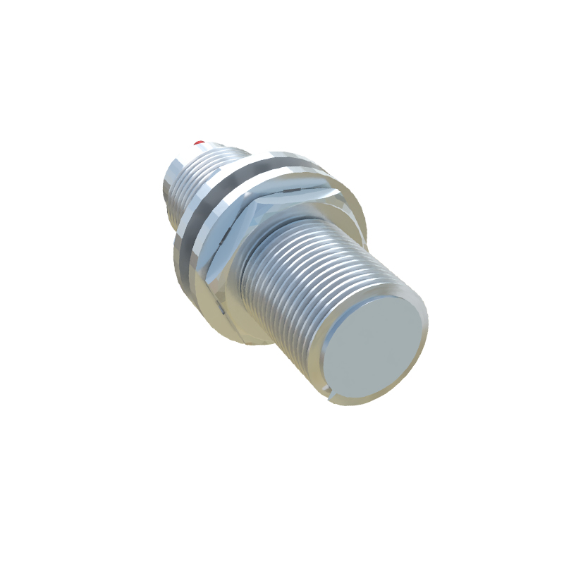
The Proximity Switch Solution: Principle and Advantages
The proposed retrofit replaces the continuous feedback sensor with a set of discrete inductive proximity switches. These solid-state devices generate an electromagnetic field and detect the presence of a metallic target—in this case, a machined lug or bolt head on the moving boom structure. When the target enters the sensing range, the switch's output state changes from OFF to ON (or vice versa). The primary advantage is the complete absence of moving parts and physical contact. Proximity switches are hermetically sealed, immune to vibration, and highly resistant to contamination from oil, grease, and dust. Their mean time between failure (MTBF) is substantially higher than that of mechanical sensors. This conversion shifts the control paradigm from continuous positioning to discrete position verification, which is often sufficient for critical safety and sequence logic.
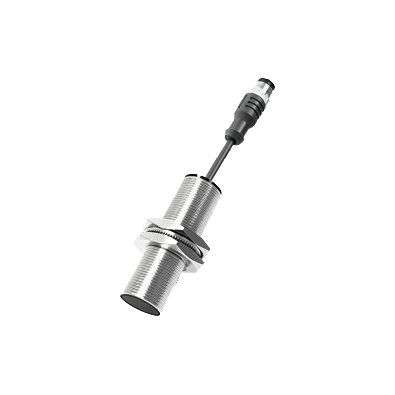
System Redesign: From Analog Feedback to Digital Logic
Implementing this change requires a fundamental redesign of the input logic within the pump's control system, typically the Programmable Logic Controller (PLC) or dedicated controller. The original system receives an analog voltage or current signal (e.g., 0-10V, 4-20mA) representing the exact boom position. The new system uses multiple proximity switches placed at strategic, predefined points: fully retracted, fully extended, and potentially one or two intermediate "zone" positions for complex folding sequences. The PLC program must be rewritten to interpret these digital ON/OFF signals. For example, the "Boom 2 Extended" command is now confirmed not by a specific voltage value, but by the activation of the "Boom 2 Full Extend" proximity switch and the deactivation of the "Boom 2 Retract" switch. This logic is inherently more fault-tolerant and easier to troubleshoot.
Practical Installation and Calibration Steps
The physical installation is straightforward. First, identify suitable mounting locations on the fixed boom structure adjacent to the moving section. These locations must be clean, rigid, and allow for consistent sensing gap adjustment (typically 1-3mm). High-grade stainless steel proximity switches with PNP (sourcing) outputs are recommended for their compatibility with common industrial PLCs and durability. Machine and weld target lugs onto the moving boom section at corresponding positions. Wiring involves running shielded cables from each switch back to the controller's digital input module, ensuring proper grounding to prevent electrical noise interference. Calibration is remarkably simple: manually position the boom to each critical point and adjust the switch or target until the indicator LED activates. No complex software scaling or linearization is needed.
Addressing Potential Challenges and Considerations
While beneficial, this conversion has important considerations. The most significant trade-off is the loss of continuous position feedback for "proportional" control features, such as extremely smooth, slow creep movements. However, for standard pouring operations, boom movement is typically at full speed between set points. Another challenge is ensuring redundancy for critical safety points; using two switches in a redundant configuration for the "fully retracted" lock position is a wise practice. Engineers must also verify the controller has sufficient spare digital input points. Finally, comprehensive documentation of the new wiring diagrams and PLC logic is essential