Understanding Through-Beam Photoelectric Sensor Operation
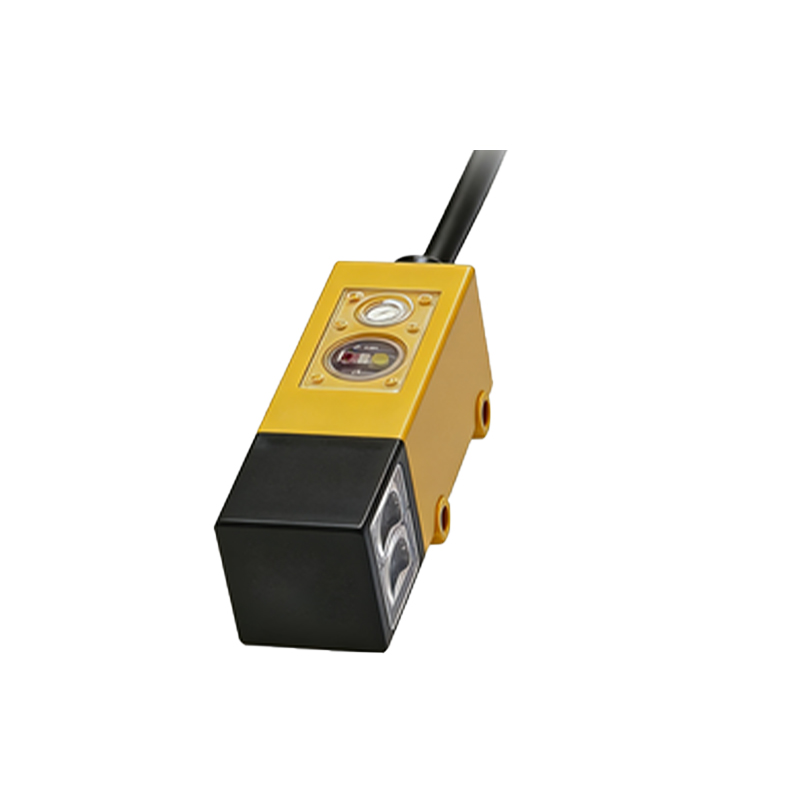
Through-beam photoelectric sensors, also known as opposed-mode sensors, are fundamental components in industrial automation. They consist of two separate units: a transmitter and a receiver. The transmitter emits a continuous beam of light, typically infrared, visible red, or laser. The receiver, positioned directly opposite the transmitter, detects this beam. The core operating principle is simple: when an object passes between the two units, it interrupts the light beam. This interruption causes the receiver's output state to change, signaling the presence of the object. This reliable "on/off" detection makes them ideal for precise object detection, counting, and safety applications where long sensing distances and high immunity to environmental factors like color or surface finish are required. The output is typically a solid-state transistor (PNP or NPN) or a relay contact that interfaces with a PLC, controller, or other machine logic.
Initial Power and Wiring Checks
When a through-beam sensor exhibits no output, the first and most critical step is to verify the electrical fundamentals. Begin by confirming that the correct power supply voltage is present at both the transmitter and receiver units. Use a multimeter to check for proper DC (e.g., 10-30 VDC) or AC voltage at the terminals, referencing the sensor's datasheet. Ensure the polarity is correct for DC sensors. Inspect all wiring connections for looseness, corrosion, or damage. A common mistake is misconnecting the load. The sensor's output switch is in series with the load (e.g., a PLC input). Verify that the load is connected to the correct output wire (often the black or blue wire) and that the common wire is properly terminated to the power supply's negative (for PNP) or positive (for NPN) terminal. A simple test is to temporarily bypass the sensor by connecting the load directly to the power supply (with appropriate current limiting) to confirm the load itself is functional.
Optical Alignment and Beam Integrity
Misalignment is the single most frequent cause of failure in through-beam applications. Even a slight angular deviation over long distances can cause the beam to miss the receiver's lens entirely. Most sensors have alignment indicators, such as a steady LED on the receiver when correctly aligned and receiving the beam. Physically check the mechanical mounting of both units for stability and vibration. Use precision alignment tools if necessary. Ensure the optical lenses are clean and free from dust, oil, condensation, or physical damage. Consider environmental factors: bright ambient light, especially direct sunlight or strobe lights, can saturate the receiver. Similarly, heavy airborne contaminants like steam, smoke, or dust can scatter or absorb the light beam. Installing protective tubes or shrouds around the beam path can mitigate these issues. For long-range sensors, verify that the detected object is large enough to fully interrupt the beam.
Diagnosing Sensor Unit Failures
If power and alignment are confirmed, the next step is to isolate which unit—transmitter or receiver—has failed. A basic method is to perform a substitution test with a known-good sensor of the same model. If this isn't possible, use a multimeter or oscilloscope. For the transmitter, you can sometimes use a digital camera (phone camera works) to view the infrared LED; it may appear as a faint purple light on the screen, confirming it is emitting. For a more precise check, measure the voltage drop across the transmitter's output LED terminals if accessible. For the receiver, monitor its output signal with a multimeter set to DC voltage while manually interrupting the beam. A functioning receiver will show a clear voltage change between its "beam received" and "beam blocked" states, as defined by its light-on/dark-on operating mode. Internal component failure due to electrical surge, excessive current, or physical shock is common. Check for any signs of overheating or burn marks on the housing or PCB.
Electrical Load and Interference Considerations
An incorrectly specified or faulty load can cause a sensor to malfunction or appear to have no output. Check the sensor's datasheet for its maximum output current and switching capacity. Exceeding these ratings can damage the internal switching transistor. Ensure the load's inrush current (e.g., from a solenoid coil or lamp) is within limits. Electrical noise from nearby motors, drives, or welding equipment can induce false signals or disrupt sensor operation. Verify that wiring is properly shielded, especially for analog outputs or long cable runs, and that shield drains are connected at one end only. Ground loops can also cause erratic behavior. Ensure all units share a common, stable ground reference. For sensors in safety circuits, remember they often have complementary outputs (NO and NC); ensure you are monitoring the correct output contact for the machine's state.
Configuration and Mode Settings
Many modern photoelectric sensors are configurable, with selectable operating modes such as Light-ON (output on when beam is received) or Dark-ON (output on when beam is blocked). An incorrectly set mode will make the sensor behave opposite to expectations. Verify the mode setting via DIP switches or teach-in buttons. Some sensors have a built-in timer function (ON-delay, OFF-delay, one-shot). If enabled, these can delay the output signal, creating the illusion of no output. Consult the manual to reset to default settings if configuration is uncertain. Additionally, check for any external control inputs that might be used to inhibit the sensor's output; these inputs may be held in a disabling state by the control system.
Systematic Troubleshooting Procedure
Follow a logical sequence to efficiently resolve the issue. Step 1: Visually inspect for obvious damage, loose connections, and dirty lenses. Step 2: Confirm power supply voltage and polarity at the sensor terminals under load. Step 3: Verify alignment using the sensor's indicator LEDs. Step 4: Test with a known-good object to block the beam, monitoring the output with a meter. Step 5: Isolate the sensor from the load to rule out load-related faults. Step 6: Swap sensor units with spares if available. Step 7: Review environmental conditions and electrical noise sources. Documenting findings at each step is crucial for identifying intermittent problems and for future maintenance reference. Persistent issues may require consultation with the sensor manufacturer's technical support, providing them with model numbers, wiring diagrams, and detailed symptom descriptions.