Understanding Proximity Sensor Operation
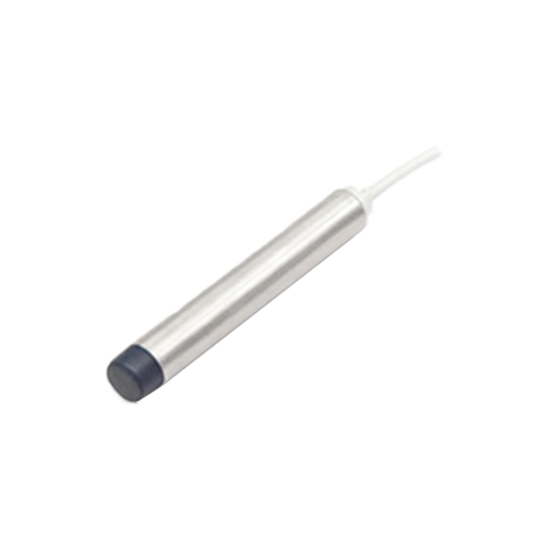
Proximity sensors are vital components in industrial automation, designed to detect the presence or absence of an object without physical contact. They typically operate by emitting an electromagnetic field or a beam of electromagnetic radiation and then looking for changes in the field or return signal. A standard inductive proximity sensor, for instance, generates an oscillating electromagnetic field from its sensing face. When a metallic target enters this field, it induces eddy currents, causing a change in the oscillation amplitude. This change is detected by the sensor's circuitry, which triggers a solid-state output switch. Normally, this output is "off" when no target is present and switches "on" when a target is detected. The persistent "on" state, or a sensor staying lit/active when it should be off, indicates a malfunction that requires troubleshooting.
Electrical Wiring and Connection Faults
Incorrect wiring is a primary culprit for a proximity sensor remaining constantly active. A common error is connecting the sensor's output to a load that exceeds its rated capacity, causing the internal switching element to fail in a closed (on) state. Similarly, a short circuit in the output wiring, either to the positive supply voltage or to ground depending on the sensor type (PNP vs. NCM), can create a permanent signal path, fooling the controller into seeing a constant target presence. Loose connections, corroded terminals, or damaged cables can also create intermittent or permanent electrical paths that mimic a valid detection signal. Always verify wiring against the manufacturer's datasheet, ensuring correct polarity, voltage levels, and load specifications.
Sensor Misapplication and Environmental Factors
Applying a sensor outside its specified operational parameters often leads to failure modes including a permanent on state. For inductive sensors, the presence of non-target metals in the sensing field—like mounting brackets, bolts, or conveyor parts—can cause constant activation. Excessive temperatures can damage internal components, causing the output transistor to latch. Harsh environments with conductive dust, metallic chips, or heavy moisture can create a bridge across the sensing face, effectively forming a constant "target." Chemical exposure may degrade the sensor's housing or potting material, leading to internal corrosion and circuit failure. Ensuring the sensor model is correctly selected for the application's environment, temperature range, and target material is crucial.
Internal Component Failure and Degradation
Like all electronic devices, proximity sensors have a finite lifespan. The core component that fails, leading to a constant on signal, is often the output switching transistor. This solid-state device can fail shorted due to voltage spikes, overcurrent, or aging. Voltage transients from inductive loads (like solenoids or relays) without proper suppression are a frequent cause. Additionally, damage to the oscillator coil or the detection circuit's integrated components can prevent the sensor from properly modulating its field, locking it in a detection state. Physical damage from impact or vibration can also cause internal solder joints to crack or components to shift, creating permanent electrical connections.
Electrical Noise and Interference Issues
Industrial environments are rich with electromagnetic interference (EMI) from motors, variable frequency drives (VFDs), welding equipment, and communication cables. This electrical noise can be coupled into the sensor's signal lines or power supply, inducing a voltage that the controller interprets as a valid "on" signal. This is particularly problematic for sensors with analog current outputs (e.g., 4-20mA) but also affects standard digital sensors. Noise can cause erratic behavior or a persistent high signal. Mitigation strategies include using shielded cables, proper grounding of the sensor body and shield, installing ferrite cores on cables, separating sensor wiring from high-power lines, and using sensors with built-in noise immunity features.
Diagnostic Steps and Troubleshooting Procedures
A systematic approach is required to diagnose a constantly active proximity sensor. First, power down the system and perform a visual inspection for obvious damage, contamination, or incorrect installation distance. Next, electrically isolate the sensor. Disconnect the output wire from the controller and use a multimeter to measure the output state relative to the supply common. If the output shows voltage (for PNP) or continuity to common (for NPN) without a target present, the sensor is faulty. Before condemning the sensor, test it in a known-good setup with a proper target. Check the power supply voltage for stability and noise. Verify the load impedance. Inspect the wiring for shorts or insulation damage. Review the installation environment for sources of interference or unintended targets.
Corrective Actions and Preventive Measures
The corrective action depends on the root cause. Replace sensors with confirmed internal failure. Rewire any incorrect or damaged circuits, ensuring proper fusing and wire