Introduction to Photoelectric Sensors in Balancing Machines
Photoelectric sensors are critical components in modern balancing machines, serving as the eyes of the system. These sensors detect the position, speed, and phase of rotating parts with high precision, enabling accurate imbalance measurement. In balancing applications, photoelectric sensors typically use infrared or laser light to identify reference marks on rotors. The sensor emits a light beam, and when the mark passes, the reflected or interrupted signal is captured. This data is then processed by the balancing machine's control unit to calculate imbalance magnitude and angle. The reliability of these sensors directly impacts the balancing accuracy, making them indispensable in industries like automotive, aerospace, and manufacturing. High-quality images of these sensors help engineers understand their design, installation, and maintenance requirements, ensuring optimal performance in demanding environments.
Types of Photoelectric Sensor Images for Balancing Machine Parts
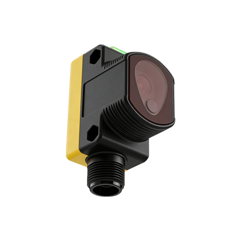
Images of photoelectric sensors for balancing machines can be categorized into several types, each serving a specific purpose. Close-up photos show the sensor's lens, housing, and connector details, highlighting build quality and material durability. Installation diagrams depict how sensors are mounted near rotors, often including alignment guides for precise positioning. Technical schematics illustrate internal components like emitters, receivers, and circuitry, aiding in troubleshooting and customization. Operational images capture sensors in action, with light beams visible during rotor rotation, demonstrating real-time detection. Comparative visuals may show different models, such as diffuse-reflective versus retro-reflective sensors, helping users select the right type for their balancing needs. These images are essential for training, procurement, and technical documentation.
Key Features Visible in Photoelectric Sensor Photos
When examining images of balancing machine photoelectric sensors, several key features stand out. The lens design is crucial, as it focuses light for accurate detection; photos often show anti-glare coatings or protective covers. Housing materials, typically made of stainless steel or rugged plastics, indicate resistance to industrial hazards like dust, oil, and vibration. Connector types, such as M12 or threaded variants, are visible in images, ensuring compatibility with machine wiring. Alignment indicators, like LED lights or markings, help in setup and calibration. Additionally, images may reveal sensitivity adjustments or diagnostic ports, allowing for fine-tuning. High-resolution photos can even show minute details like sealing ratings (e.g., IP67), which are vital for operation in harsh conditions. These visual cues enable engineers to assess sensor suitability quickly.
Applications and Benefits of Photoelectric Sensors in Balancing
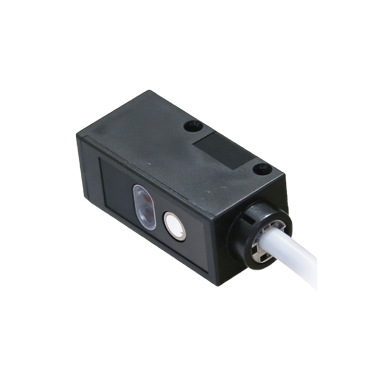
Photoelectric sensors play a pivotal role in balancing machines across various applications. In automotive manufacturing, they ensure crankshafts and flywheels are balanced for smooth engine operation. For aerospace, sensors help balance turbine blades and propellers, enhancing safety and efficiency. Industrial fans and pumps rely on these sensors to minimize vibration, reducing wear and noise. The benefits include high-speed detection, with some sensors operating at frequencies exceeding 10 kHz, allowing for real-time imbalance correction. Non-contact measurement prevents part damage, and immunity to electromagnetic interference ensures reliability. Images of sensors in these applications showcase their integration into automated systems, highlighting how they contribute to precision and productivity. This visual context underscores their importance in achieving tight balancing tolerances.
Maintenance and Troubleshooting Through Sensor Imagery
Images are invaluable for maintaining and troubleshooting photoelectric sensors in balancing machines. Visual guides can show common issues like lens contamination from oil or debris, which may cause signal loss. Photos of damaged cables or connectors help identify wear points, prompting preventive replacements. Alignment check images demonstrate proper positioning relative to rotor marks, preventing misalignment errors. For troubleshooting, step-by-step image sequences illustrate cleaning procedures, sensitivity adjustments, or replacement steps. Comparative before-and-after photos highlight the impact of maintenance on performance. Additionally, thermal images might reveal overheating due to electrical faults. By leveraging these visuals, technicians can quickly diagnose problems, reduce downtime, and extend sensor lifespan, ensuring consistent balancing accuracy.
Selecting Photoelectric Sensors Based on Image Analysis
Choosing the right photoelectric sensor for a balancing machine often involves analyzing images to match specifications. Photos reveal physical dimensions, ensuring the sensor fits into confined spaces near rotors. Beam range and spot size visible in operational images indicate detection capabilities for different rotor sizes. Environmental ratings, like ingress protection labels, are often captured in close-ups, confirming suitability for wet or dusty areas. Images showing mounting brackets or accessories aid in planning installation. Furthermore, visuals of sensor outputs, such as digital displays or signal graphs, help assess compatibility with control systems. By studying these images, engineers can make informed decisions, selecting sensors that enhance balancing precision and durability. This visual selection process reduces errors and optimizes machine performance.