Understanding the 21 Proximity Sensor
The 21 series proximity sensor is a widely used inductive sensor designed for non-contact detection of metallic objects. Its robust construction and reliable performance make it a staple in industrial automation, machine tools, and material handling systems. Calibration is not a routine task for most standard applications, as these sensors are typically pre-set at the factory. However, precise calibration becomes critical in high-precision applications, after sensor replacement, or when environmental conditions or target material properties deviate significantly from the standard setup. Proper calibration ensures the sensor triggers at the exact intended distance, maximizing system reliability and preventing false triggers or missed detections.
Pre-Calibration Preparation and Safety
Before initiating any calibration procedure, comprehensive preparation is essential. First, consult the specific sensor's datasheet from the manufacturer. Key parameters include the nominal sensing distance (Sn), operating voltage, output type (PNP/NPN, NO/NC), and any special characteristics. Ensure the power supply is disconnected and locked out following proper safety protocols (LOTO). Gather the necessary tools: a set of certified gauge blocks or precision shims made of the correct target material (usually mild steel), a stable mounting fixture, a multimeter or an oscilloscope for output verification, and the required adjustment tool (often a small potentiometer or a teach-in button). The workspace should be clean, free from metallic debris, and other electromagnetic interference sources should be minimized.
Establishing the Reference Setup
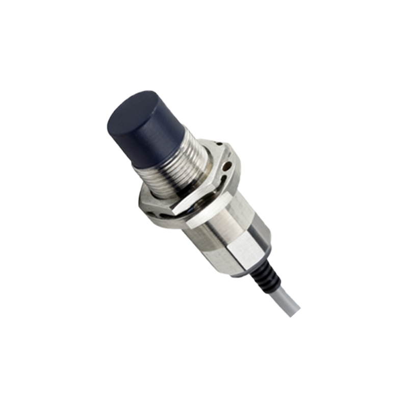
Mount the sensor securely in its final operational fixture or a calibration jig that replicates the installation. It is crucial that the mounting is rigid, as any vibration or movement will affect calibration accuracy. Connect the sensor to its specified power supply and, if applicable, connect your measuring device (multimeter) to monitor the output signal. Prepare the standard target. For a 21 series sensor, this is typically a square piece of mild steel (Fe 360) with a thickness of 1mm and side lengths equal to the sensor's face diameter or as specified in the datasheet. The target must approach the sensor axially, perpendicular to the sensing face.
Performing the Calibration Procedure
Begin by positioning the standard target at a distance greater than the rated sensing range. Power on the sensor. Slowly and steadily move the target towards the sensing face. Use the gauge blocks to ensure precise distance control. Observe the output state. The point at which the output switches (from OFF to ON for normally open, or ON to OFF for normally closed) is the actual sensing point. Locate the sensor's adjustment element. For models with a potentiometer, use a non-metallic screwdriver. Turn the potentiometer clockwise to decrease the sensing distance or counter-clockwise to increase it. For "teach-in" models, bring the target to the desired trigger point and press the teach button as per instructions. Repeat the approach and retract cycle several times to verify consistency.
Verification and Hysteresis Check
After adjustment, a full verification cycle is mandatory. Measure the precise distance at which the sensor activates as the target approaches (the "operate point"). Then, slowly retract the target and note the distance at which the sensor de-activates (the "release point"). The difference between these two distances is the sensor's hysteresis. This built-in hysteresis prevents output oscillation when a target is at the critical sensing edge. Verify that both the operate point and the hysteresis value are within the tolerances required for your application. Test with multiple approach speeds and ensure the output is clean and chatter-free.
Documentation and Final Considerations
Record all calibration data: sensor model, serial number, date, calibrated sensing distance, applied voltage, target material, hysteresis measured, and the technician's name. This log is vital for traceability and future maintenance. Re-install the sensor in its operational environment if it was calibrated on a bench. Perform a final functional test in the actual machine or process, using the real target under normal operating conditions. Be aware that factors like extreme temperatures, different target materials (e.g., aluminum, stainless steel), and the presence of coatings can affect sensing performance. For non-standard targets, a correction factor from the datasheet must be applied, and recalibration for that specific condition may be necessary.