Introduction to Photoelectric Sensors in CAD Design
In the realm of industrial automation and electrical engineering design, Computer-Aided Design (CAD) software serves as the fundamental tool for creating precise and standardized schematics. Photoelectric sensors, critical components for detection, positioning, and counting in automated systems, must be accurately represented within these drawings. Their CAD symbols are not merely graphical placeholders; they are a universal language that conveys function, electrical characteristics, and interconnection points to engineers, technicians, and procurement specialists worldwide. A standardized symbol ensures clarity, reduces errors during the panel building and installation phases, and facilitates seamless communication across global projects. Understanding these symbols is therefore paramount for any professional involved in the design or implementation of control systems.
Standard Symbol Conventions and Libraries
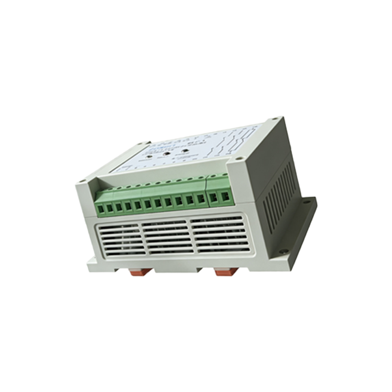
The representation of photoelectric sensors in CAD typically follows international standards, most notably those set by the International Electrotechnical Commission (IEC). While specific graphic details can vary slightly between different CAD software libraries (e.g., AutoCAD Electrical, EPLAN, SolidWorks Electrical), the core principles remain consistent. A photoelectric sensor symbol generally comprises a circle or a square representing the sensor body. Key functional elements are then added. For the optical emitter, a simple diode symbol (a triangle pointing away from the body with a line) is often used. For the receiver, a phototransistor or photodiode symbol (a diode symbol within a circle or with two arrows pointing inward) is standard. The type of sensing beam—diffuse, retro-reflective, or through-beam—is usually indicated by accompanying graphical lines or annotations near the symbol.
Decoding Common Photoelectric Sensor Symbols
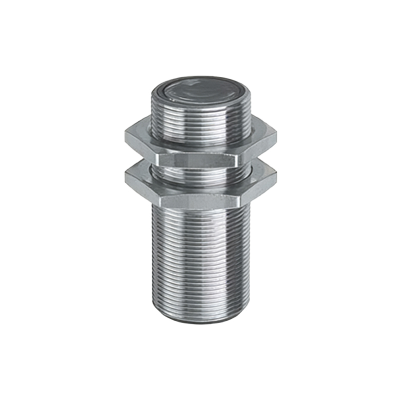
Breaking down the symbols by sensing mode provides practical insight. A *through-beam sensor* symbol typically shows two separate symbols: one for the emitter and one for the receiver, placed opposite each other in the drawing, with a dashed or dotted line representing the light beam connecting them. A *retro-reflective sensor* symbol often depicts a single unit with both emitter and receiver elements, alongside a small graphical representation of a reflector (like a triangle) opposite it. A *diffuse sensor* symbol, also a single unit, may include curved lines emanating from the front to indicate the reflection of light from the target object. Furthermore, symbols differentiate between output types: a transistor (NPN or PNP) output is shown with a specific transistor symbol inside the main body, while a relay contact output might be represented by a switch symbol. Power supply terminals (V+ and V- or L+ and L-) and output signal lines are clearly marked.
Connection Diagrams and Terminal Designations
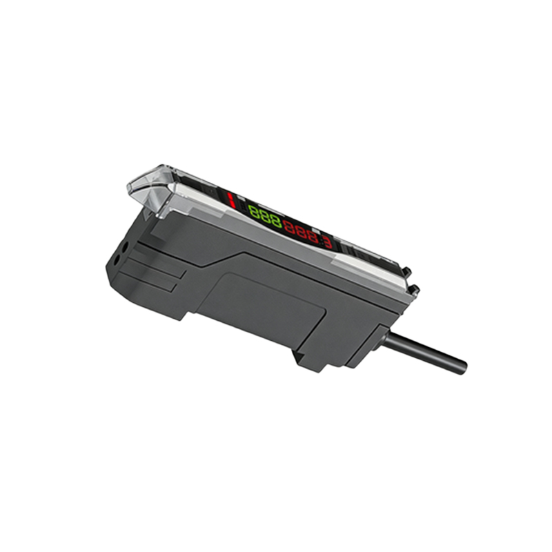
Beyond the basic device symbol, detailed connection diagrams are crucial. These diagrams show the internal circuitry and the precise terminal points for wiring. A standard 3-wire DC sensor symbol, for instance, will explicitly label the three connections: brown wire for positive supply (+V), blue wire for negative supply (0V or common), and black wire for the switched output signal. For 4-wire models with both a Normally Open (NO) and a Normally Closed (NC) output, two output lines are shown. The CAD symbol library should link this graphical representation to a parts database, automatically populating fields for part numbers, voltage ratings, and output current. This integration between the symbol and data management is a key efficiency feature of professional electrical CAD systems.
Best Practices for Using Symbols in Schematics
Effective use of photoelectric sensor symbols requires adherence to several best practices. First, always utilize symbols from the CAD software's certified or company-standard library to maintain consistency. Second, ensure every symbol is properly annotated with a unique component tag, such as "B1" for a sensor, which links to a parts list. Third, clearly indicate the sensing range and orientation in a mechanical drawing or a note if it impacts wiring layout. Fourth, for complex systems, consider using macro symbols or function blocks that combine the sensor with its associated evaluation unit or safety relay circuitry. Finally, always cross-reference the CAD symbol with the manufacturer's datasheet to confirm terminal assignments and functional logic, especially for specialized sensors like background suppression or color detection models.
Impact on System Documentation and Maintenance
Accurate CAD symbols form the backbone of all subsequent system documentation. From the initial schematic, bills of materials are generated, panel layouts are derived, and cable schedules are created. For maintenance technicians, a correctly drawn schematic with intuitive symbols is an indispensable troubleshooting guide. It allows them to quickly identify a sensor's location in the circuit, understand its normal operating state, and trace wiring faults. In an era of digital twins and integrated plant documentation, the humble CAD symbol evolves into a smart object, potentially holding links to calibration certificates, maintenance history, or even real-time diagnostic data. Thus, the diligence applied in selecting and placing the correct photoelectric sensor symbol during the design phase pays continuous dividends throughout the asset's lifecycle.