Introduction to 4-Wire M10 Proximity Sensors
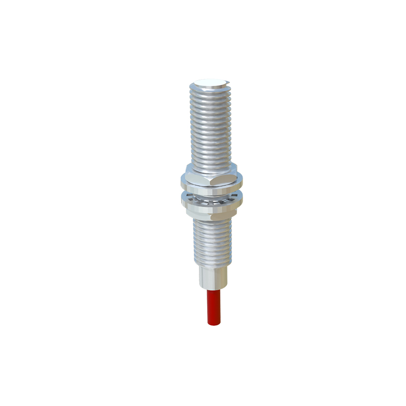
In the realm of industrial automation and control systems, proximity sensors are indispensable components for non-contact object detection. Among the diverse range of form factors and wiring configurations, the 4-wire M10 inductive proximity sensor stands out for its versatility and reliability. Characterized by its compact 10mm cylindrical threaded barrel housing, this sensor type is engineered to detect metallic objects without physical contact. The "4-wire" designation is crucial, indicating a specific circuit design that provides distinct advantages in certain applications. Unlike 2-wire or 3-wire variants, the 4-wire sensor incorporates separate power supply lines and output lines, offering enhanced functionality and simplified integration into complex control circuits. This architecture typically allows for both normally open (NO) and normally closed (NC) output configurations from a single device, providing greater flexibility for system designers.
Internal Circuitry and Operating Principle
The core of an M10 inductive proximity sensor is an oscillator circuit, a demodulator, and a solid-state output switch. When powered, the oscillator generates a high-frequency electromagnetic field at the active face of the sensor. The presence of a metallic target within the specified sensing range disturbs this field, causing a change in the oscillation amplitude. This change is detected by the demodulator, which then triggers the output switching circuit. In a 4-wire DC sensor, the wiring typically consists of two power leads (brown for positive/+, blue for negative/- or 0V) and two output leads (black and white). One output provides a normally open function, while the other provides a normally closed function. This dual-output capability is a direct result of the independent output transistor design enabled by the four-wire system, allowing the sensor to simultaneously provide complementary signals to a Programmable Logic Controller (PLC) or other control device.
Key Advantages and Application Benefits
The primary benefit of the 4-wire M10 configuration lies in its wiring flexibility and output options. Engineers can select either the NO or NC signal based on the safety and logic requirements of the machine control sequence without needing to change the sensor physically. This simplifies inventory and allows for last-minute logic changes. Furthermore, because the output circuit is electrically isolated from the power supply circuit, it often provides superior protection against wiring errors and electrical noise, leading to increased system stability. The M10 size is particularly advantageous in space-constrained installations, such as on small robotic end-effectors, within compact machinery, or on densely populated control panels. Its robust metallic housing, typically made of nickel-plated brass or stainless steel, ensures high resistance to mechanical impacts, coolant, and oil, making it suitable for harsh industrial environments like machining centers and assembly lines.
Wiring and Installation Guidelines
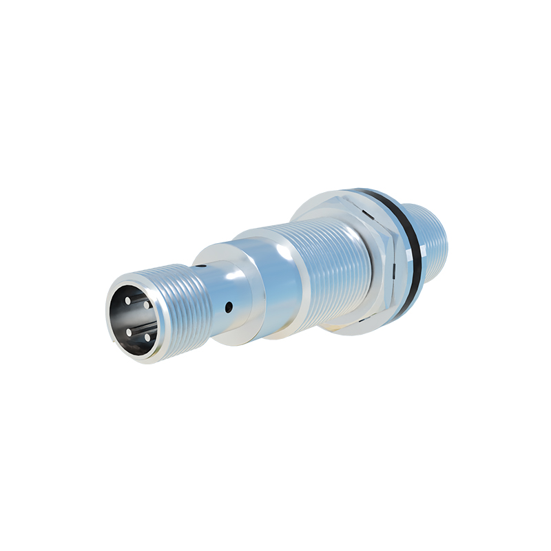
Correct installation is paramount for optimal performance. The M10 sensor is designed to be mounted by threading it into a standard M10x1.0 tapped hole. It is critical to ensure the sensing face has adequate clearance from surrounding metal to avoid false triggering, typically a distance of one to two times the sensor's diameter. When wiring, always refer to the manufacturer's datasheet. A standard color code for a DC 4-wire sensor is: Brown wire to DC positive (e.g., +24V), Blue wire to DC negative (0V), Black wire as the normally open (NO) output, and White wire as the normally closed (NC) output. The output loads (like a PLC input, relay coil, or indicator lamp) are connected between the chosen output wire and the positive supply or ground, depending on the sensor's sinking (PNP) or sourcing (NPN) configuration. Proper shielding and routing of cables away from high-power lines are recommended to minimize electromagnetic interference.
Technical Specifications and Selection Criteria
When specifying a 4-wire M10 proximity sensor, several key parameters must be evaluated. The sensing distance, or "Sn," is standardized; for a standard M10 inductive sensor, this is typically 1.5mm to 2mm for steel targets. The operating voltage range (e.g., 10-30V DC) must be compatible with the plant's control voltage. The output current rating (often 200mA) must not be exceeded. The switching frequency defines how quickly the sensor can detect objects passing by, which is vital for high-speed counting applications. Environmental ratings, particularly the Ingress Protection (IP) rating (like IP67), indicate the level of protection against dust and water immersion. For specific applications, engineers may also need to consider factors like target material correction factors (steel, aluminum, copper), temperature range, and short-circuit and reverse polarity protection features.