Understanding the Core Components
A photoelectric sensor, often colloquially referred to as an "electric eye," is a device that uses a light beam to detect the presence, absence, or distance of an object. Its operation hinges on three fundamental components: an emitter (light source), a receiver (photodetector), and associated control circuitry. The emitter projects a beam of light—commonly visible red, infrared, or laser—towards the receiver. When an object interrupts or reflects this beam, it alters the light's intensity at the receiver. This change is converted by the photodetector into an electrical signal, which is then processed by the control circuitry to produce a discrete output, typically a switch closure or a change in voltage/current. Understanding this basic principle is the first step toward effective application.
Selecting the Appropriate Sensing Mode
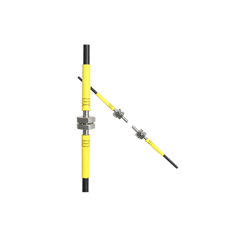
Choosing the correct sensing mode is critical for reliable operation. There are three primary modes: through-beam, retro-reflective, and diffuse (proximity). Through-beam sensors consist of separate emitter and receiver units placed opposite each other. An object is detected when it breaks the beam. This mode offers the longest sensing range and highest reliability, ideal for harsh environments. Retro-reflective sensors house both emitter and receiver in one unit, using a reflector to bounce the beam back. Detection occurs when the beam is blocked. They are easier to install than through-beam but can be fooled by shiny objects. Diffuse sensors rely on the reflection of light from the target itself. Both emitter and receiver are in one housing, making them compact and easy to install for close-range detection of non-reflective objects.
Installation and Alignment Best Practices
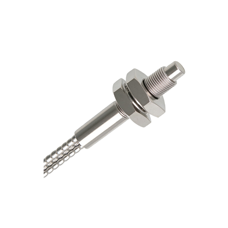
Proper installation ensures optimal performance and longevity. First, securely mount the sensor and, if applicable, the reflector or receiver using appropriate brackets to minimize vibration. For through-beam and retro-reflective types, precise alignment is paramount. Use the sensor's built-in alignment indicators (often LED lights). A common technique is to roughly align the units, then fine-tune until the "receive" or "stability" LED indicates maximum signal strength. Ensure the light path is clear of obstructions like dust, steam, or incidental moving parts. Consider the sensing environment: use sensors with suitable ingress protection (IP) ratings for dusty or wet areas, and avoid mounting near strong ambient light sources that could interfere with the beam.
Electrical Wiring and Connection
Photoelectric sensors are available in various output configurations: NPN (sinking), PNP (sourcing), analog, or relay outputs. Always consult the datasheet to match the sensor's output type with your control system's input requirements (e.g., a PLC). Connect the power supply within the specified voltage range, typically 10-30V DC or 90-250V AC. Observe correct polarity for DC models. Proper grounding is essential to shield against electrical noise. For long cable runs in electrically noisy environments, use shielded cables and connect the shield to ground at one end only. Always implement protective circuits, such as fuses or surge suppressors, especially in industrial settings with inductive loads to prevent damage from voltage spikes.
Configuration and Sensitivity Adjustment
Most modern photoelectric sensors feature potentiometers or teach-in buttons for sensitivity (gain) adjustment and timing functions. Sensitivity adjustment controls the threshold at which the sensor triggers. Set it high enough to reliably detect the target but low enough to ignore background interference or slight dust accumulation. Many sensors have a stability indicator to aid this setup. Timing functions like ON-delay or OFF-delay can be configured to "debounce" the signal, ensuring a stable output despite target vibration or rapid fluttering. For challenging applications with transparent objects or varying colors, sensors with background suppression or true color recognition technology may be necessary.
Troubleshooting Common Issues
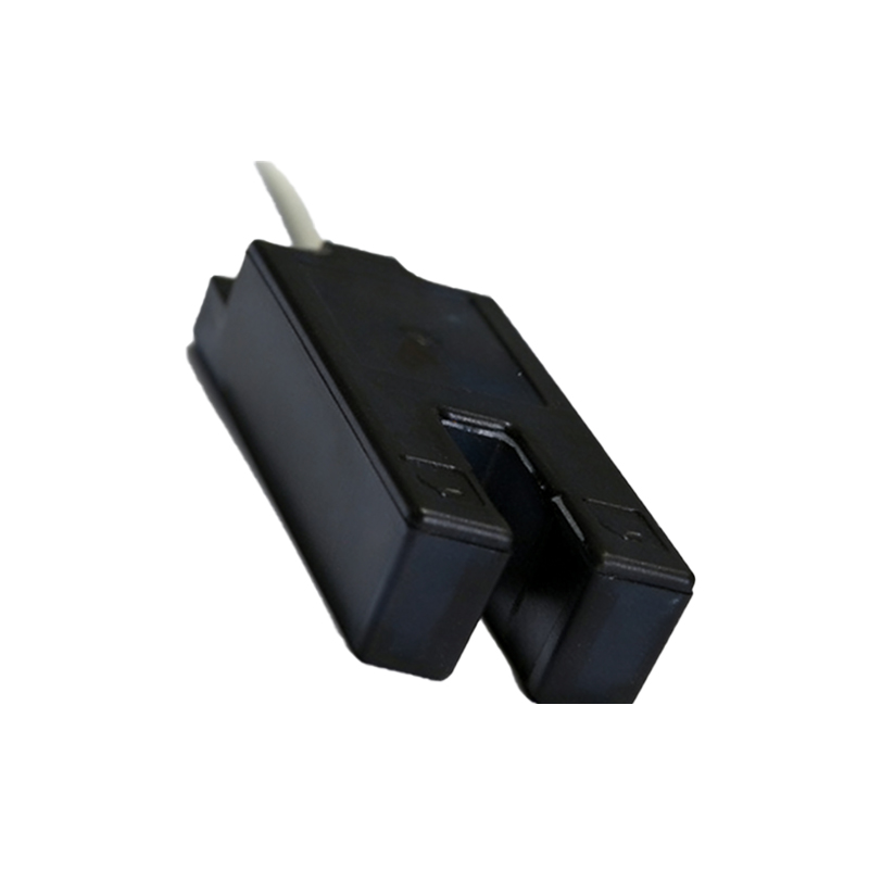
Even well-installed sensors can encounter problems. A systematic approach is key. If the sensor fails to detect, first verify power and wiring. Check alignment using the indicator LEDs; realign if necessary. Inspect the lens for dirt or damage and clean it with a soft cloth. For diffuse sensors, ensure the target material and color are within the sensor's specified reflectivity range. Intermittent operation often points to electrical noise, unstable power supply, or a marginal alignment—recheck grounding and cable routing. If the sensor triggers without a target present (false triggering), reduce the sensitivity, shield it from ambient light, or check for reflective surfaces in the sensing field. Always refer to the manufacturer's diagnostic guides.
Advanced Applications and Integration
Beyond simple presence detection, photoelectric sensors enable sophisticated automation. They can be used for precise edge guiding in web processing, small part counting on high-speed conveyors, and bottle cap inspection on filling lines. Analog output sensors provide continuous distance measurement for positioning tasks. By integrating sensor outputs into a PLC or PC-based control system, complex logic can be implemented, such as initiating a robotic pick-and-place sequence or sorting items by height using multiple sensors. Selecting sensors with specialized beams (e.g., narrow, concentrated) or communication capabilities (IO-Link) can provide diagnostic data and parameterization from the control level, facilitating predictive maintenance and faster changeovers.