Understanding Sensor Power Requirements
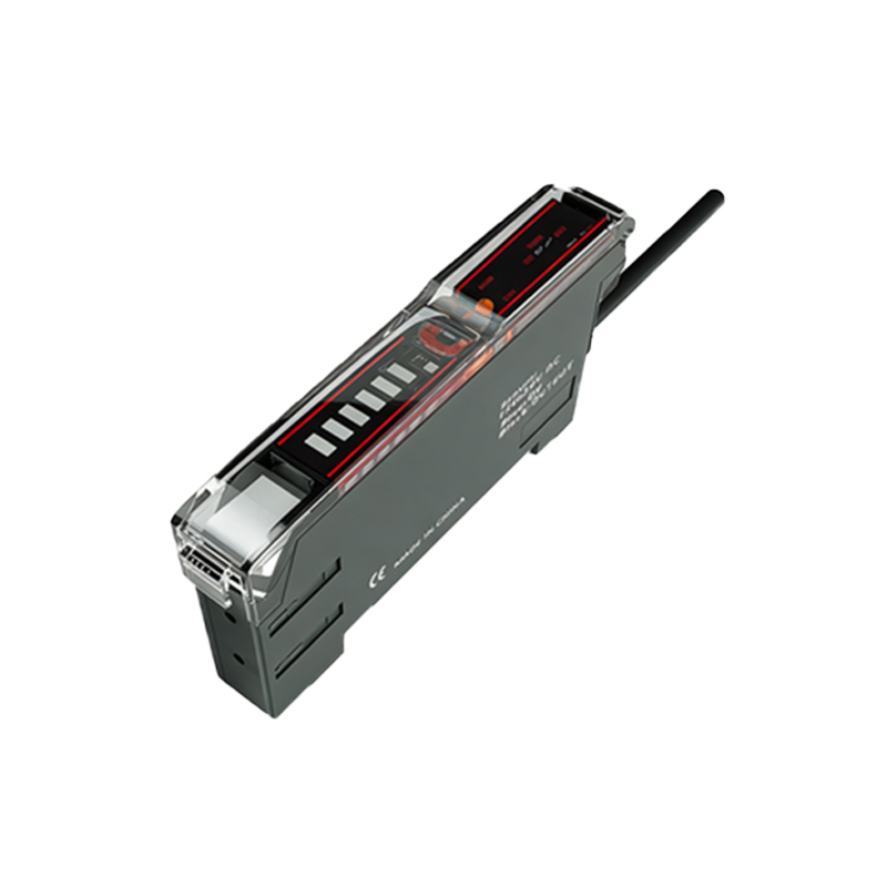
Before connecting a photoelectric sensor to an external power supply, it is crucial to thoroughly understand its specific power requirements. This information is always detailed in the sensor's datasheet or technical manual. Key parameters to identify include the operating voltage range (commonly 10-30 VDC for DC models or 90-250 VAC for AC models), current consumption (typically in milliamperes), and whether the sensor requires a regulated or unregulated power supply. For DC sensors, polarity is also a critical factor; incorrect connection can permanently damage the device. Always verify if the sensor is a 2-wire, 3-wire, or 4-wire type, as this determines the wiring configuration. A 3-wire sensor, the most common, will have separate wires for power positive (brown), power negative/ground (blue), and output signal (black). Ignoring these specifications risks sensor malfunction, reduced lifespan, or immediate failure.
Selecting an Appropriate Power Supply
Choosing a suitable external power supply is the next critical step. The power supply's output voltage must fall within the sensor's specified operating range. For instance, if a sensor operates at 12-24 VDC, a 24 VDC power supply is often an optimal choice, providing headroom for minor voltage drops in the wiring. The power supply's current rating must exceed the total current draw of all connected sensors. Calculate the total load by summing the current consumption of each sensor and adding a safety margin of at least 20%. For industrial environments, consider using a regulated, switched-mode power supply with protection features like overload, short-circuit, and overvoltage protection. Ensure the power supply is properly rated for the installation environment (e.g., IP rating for dust/water resistance) and complies with relevant safety standards.
Wiring and Connection Procedures
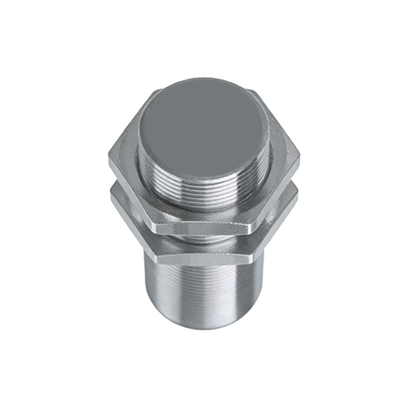
Proper wiring is essential for reliable operation. First, ensure all power is disconnected. For a standard 3-wire DC sensor: Connect the brown wire to the positive terminal (+) of the DC power supply. Connect the blue wire to the negative terminal (-) or ground of the power supply. The black wire is the output signal and should be connected to the load (e.g., a PLC input, relay, or indicator). The load's other side is then connected back to the power supply negative, completing the circuit. Use shielded cables in electrically noisy environments, connecting the shield to ground at only one end to prevent ground loops. Secure all connections with appropriate terminals (e.g., screw terminals, crimp connectors) and avoid loose strands that could cause short circuits. Always follow the manufacturer's wiring diagram precisely.
Implementing Protective Measures
To ensure long-term stability and protect both the sensor and connected equipment, incorporate protective components into the circuit. For DC sensors driving inductive loads like relays or solenoids, install a flyback diode across the load to suppress voltage spikes. In cases where the sensor output connects to a PLC, a surge suppressor may be necessary. Fusing the power supply line is a fundamental safety practice; select a fast-acting fuse with a current rating slightly above the sensor's maximum consumption. For sensors in harsh environments, consider using a separate, isolated power supply to prevent noise interference from other machinery from affecting the sensor's performance. Proper grounding of the power supply and sensor housing (if metallic) is mandatory to shield against electromagnetic interference and enhance safety.
Verification and Troubleshooting
After completing the connections, perform a systematic verification. Restore power and observe the sensor's status LED (if equipped). Most sensors have a power/stable operation indicator. Test the sensor's function by interrupting its light beam or reflecting surface and confirm the output signal changes state as expected, which can be checked with a multimeter or by observing the controlled load. Common issues include no power (check fuse, wiring polarity, and voltage at sensor terminals), unstable operation (often caused by insufficient current, electrical noise, or incorrect sensing object/material), and intermittent faults (check for loose connections or damaged cables). Always refer to the troubleshooting guide in the sensor manual. Documenting the wiring setup aids future maintenance.