Understanding Proximity Sensors and PLC Inputs
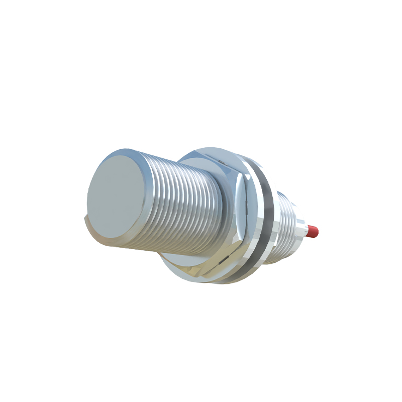
Proximity sensors are fundamental components in industrial automation, providing non-contact detection of metallic or other objects. When integrating these sensors with a Mitsubishi PLC, such as the FX series or the newer iQ-R/F/L series, a clear understanding of both the sensor's output type and the PLC's input specifications is paramount. Proximity sensors typically come in two output configurations: NPN (sinking) and PNP (sourcing). An NPN sensor switches the negative or 0V line to the load, while a PNP sensor switches the positive voltage line. The PLC's input module must be compatible with this choice. Most Mitsubishi PLC DC input modules are designed as sinking inputs (common to 24V), meaning they are internally connected to positive voltage, and thus typically require an NPN sensor to complete the circuit by providing the 0V connection. Confirming this compatibility from the hardware manuals is the essential first step before any physical connection is made.
Wiring an NPN Proximity Sensor to a Mitsubishi PLC
For a standard 3-wire DC NPN normally-open (NO) proximity sensor, the wiring procedure is straightforward. The brown wire (typically) is connected to the positive DC supply voltage, usually +24VDC. The blue wire is connected to the 0V or negative side of the same DC supply. The black wire is the signal output wire. This black wire from the sensor is connected directly to the desired input terminal on the Mitsubishi PLC (e.g., X0). The PLC input's common terminal (often labeled as "S/S" or "COM") must be connected to the positive side of the power supply (+24VDC). This configuration creates a circuit where, when the sensor detects an object, its NPN transistor activates, connecting the PLC input (X0) to 0V. This current flow from the PLC's internal circuitry through the input point to the sensor's 0V line registers as an "ON" or logical "1" state in the PLC's input image area. Always ensure the power supply is isolated and properly rated for both the sensor and the PLC input circuit.
Wiring a PNP Proximity Sensor to a Mitsubishi PLC
Wiring a PNP sensor requires a different configuration of the PLC's input common terminal. For a 3-wire DC PNP normally-open sensor, the brown wire again connects to +24VDC, and the blue wire to 0V. The black signal output wire, which now outputs +24V when active, is connected to the PLC input terminal (X0). The critical difference is that the PLC input common terminal ("S/S" or "COM") must be connected to the 0V side of the power supply. When the PNP sensor detects an object, it supplies +24V to the PLC input terminal. The current then flows from this terminal, through the PLC's internal input circuitry, to the now-0V common terminal, completing the circuit and activating the input. Attempting to connect a PNP sensor to a sinking-input PLC module with the common set to +24V will result in no operation or potential damage. Some Mitsubishi PLC input modules are switchable between sourcing (for PNP) and sinking (for NPN) modes via a physical connector or software setting, offering greater flexibility.
Considerations for 2-Wire AC Sensors and Shielded Cables
While less common in new DC systems, 2-wire AC proximity sensors are also used. Connecting these to a Mitsubishi PLC requires an AC input module. One sensor wire connects to the AC power source (often 100-240VAC), and the other wire connects to the PLC input terminal and then to the neutral line through the PLC's internal circuit. It is vital to check the leakage current of the 2-wire sensor; if it is too high, it may prevent the PLC input from turning off reliably, necessitating a bypass resistor. Furthermore, for all sensor types, especially in electrically noisy industrial environments, the use of shielded cable is strongly recommended. The cable shield should be grounded at only one end, typically at the PLC cabinet's ground terminal, to prevent ground loops. This practice minimizes electromagnetic interference (EMI) from motors or frequency inverters, which could cause erratic input signals and machine malfunctions.
Testing and Troubleshooting the Connection
After completing the wiring, a systematic test is crucial. Apply power to the system. On the Mitsubishi PLC, the status of the input LEDs (usually located