Understanding SLCK Photoelectric Sensor Fundamentals
Photoelectric sensors, such as the SLCK series, are pivotal components in industrial automation, utilizing light beams to detect the presence, absence, or distance of objects. These sensors operate on the principle of emitting a light signal—typically infrared, visible red, or laser—and analyzing the reflected or received light. The SLCK models often feature adjustable sensing ranges, response times, and output configurations (like NPN or PNP). Before initiating any debugging process, it is crucial to thoroughly review the sensor's datasheet to confirm its specifications, including power supply requirements (commonly 10-30V DC), output type, and environmental ratings (IP67 for dust and water resistance). A solid grasp of these basics ensures that subsequent troubleshooting steps are grounded in accurate technical knowledge, preventing misdiagnosis due to incorrect assumptions about the sensor's capabilities.
Initial Setup and Power Connection Checks
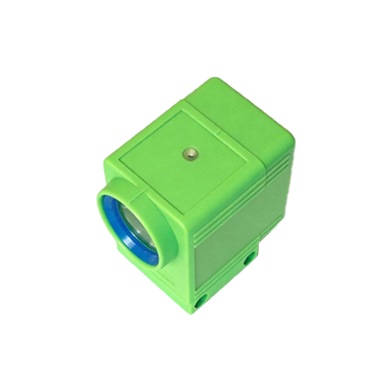
Begin the debugging procedure by verifying the power supply connections. Ensure that the SLCK sensor is wired correctly according to the manufacturer's diagram—typically involving V+ (positive), V- (negative or ground), and output terminals. Use a multimeter to measure the voltage at the sensor's terminals; it should fall within the specified range (e.g., 12-24V DC). Fluctuations or deviations can lead to erratic behavior. Additionally, inspect the wiring for loose connections, frayed cables, or short circuits, as these are common culprits for sensor failure. If the sensor has an indicator LED, observe its status: a steady or blinking light often signifies proper power, while no illumination suggests a power issue. This step eliminates basic electrical faults before delving into more complex operational problems.
Aligning the Sensor and Target Object
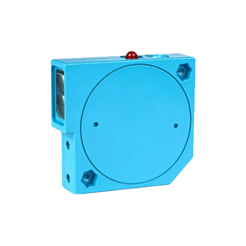
Misalignment is a frequent cause of photoelectric sensor malfunctions. For SLCK sensors, precise alignment between the emitter and receiver (in through-beam types) or the sensor and reflective surface (in retro-reflective or diffuse models) is essential. Start by positioning the target object within the specified sensing range, ensuring it is perpendicular to the sensor's lens. Use alignment tools or manual adjustments to fine-tune the angle. For diffuse sensors, consider the target's color and material, as dark or non-reflective surfaces may require sensitivity adjustments. It is advisable to perform alignment in the actual operating environment, as ambient conditions like dust or vibration can affect performance. Document the optimal position once achieved to facilitate future maintenance.
Adjusting Sensitivity and Response Time
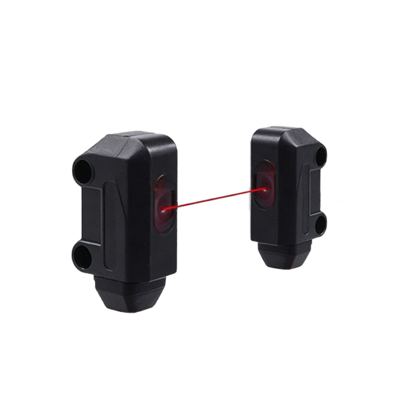
Most SLCK photoelectric sensors feature potentiometers or digital interfaces for sensitivity and response time adjustments. Sensitivity controls the threshold at which the sensor detects an object; if set too high, it may trigger falsely due to background interference, while too low a setting can cause missed detections. Gradually adjust the potentiometer while testing with the target object, using the sensor's output indicator to verify transitions. Response time settings determine how quickly the sensor reacts to changes; for high-speed applications, shorten the response time, but be cautious of potential noise interference. Refer to the technical manual for specific calibration procedures, as improper adjustments can lead to unstable operation. Regularly monitor these settings over time, as environmental factors like temperature shifts may necessitate recalibration.
Testing Output Signals and Load Integration
Once the sensor is powered and aligned, test its output signal to ensure it interfaces correctly with the control system (e.g., PLC, relay, or controller). Connect the output to the intended load and use a multimeter or oscilloscope to verify the signal voltage and waveform. For digital outputs, check that the signal switches cleanly between on/off states without chatter or delay. If the sensor incorporates programmable functions, such as timers or logic operations, validate these features through simulated scenarios. Ensure that the load's current draw does not exceed the sensor's maximum rating to prevent damage. In cases of inconsistent output, consider external factors like electrical noise from nearby motors or frequency inverters, which may require shielding or filtering solutions.
Environmental Interference and Mitigation Strategies
Industrial environments often introduce challenges such as ambient light, dust, moisture, or electromagnetic interference (EMI) that can disrupt SLCK sensor performance. To mitigate ambient light issues, select sensors with modulated light sources or use shades/barriers. For dusty or humid conditions, confirm the sensor's IP rating is adequate and clean lenses regularly. EMI from heavy machinery can be addressed by routing cables away from power lines, using shielded cables, and grounding properly. Additionally, consider temperature extremes; operating outside the specified range may cause drift or failure. Implementing these proactive measures during installation reduces debugging needs and enhances long-term reliability.
Documentation and Preventive Maintenance Practices
Effective debugging extends beyond immediate fixes to include thorough documentation and preventive maintenance. Record all adjustments, test results, and environmental conditions during the debugging process for future reference. Establish a routine maintenance schedule that includes visual inspections, cleaning of optical components, and verification of electrical connections. Train personnel on basic troubleshooting steps to minimize downtime. By adopting a systematic approach, engineers can not only resolve current issues with SLCK photoelectric sensors but also anticipate and prevent potential failures, ensuring continuous operation in automated systems.