Understanding Proximity Switch Fundamentals
Proximity switches, also known as proximity sensors, are non-contact electronic devices designed to detect the presence or absence of objects within a specified sensing range. Unlike mechanical limit switches, they operate without physical contact, making them ideal for harsh industrial environments where durability and reliability are paramount. These sensors function based on various principles, including inductive, capacitive, and magnetic (reed or Hall effect) technologies. Inductive sensors detect metallic objects, capacitive sensors can detect both metallic and non-metallic materials, and magnetic sensors respond to permanent magnets. The core advantage lies in their wear-free operation, high switching frequency, and resistance to contaminants like dust, oil, and moisture. Selecting the correct sensor type is the first critical step before examining any wiring configuration, as the underlying technology dictates the electrical characteristics and compatibility with control systems.
Key Components and Terminal Identification
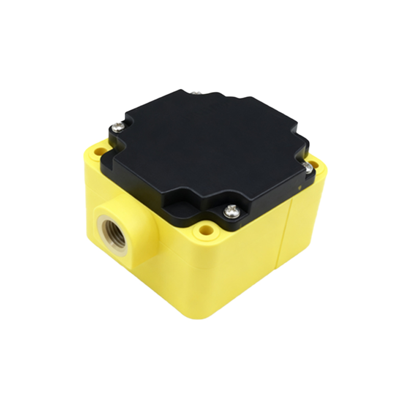
A standard three-wire DC proximity switch typically features three distinct terminals: brown (or red) for positive supply voltage (V+), blue for common negative or ground (0V), and black (or white) for the output signal. For AC-powered sensors, common wire colors include brown (live), blue (neutral), and black (output). Two-wire AC/DC sensors integrate the supply and load in series, simplifying installation but requiring careful load matching. It is imperative to consult the manufacturer's datasheet, as color codes can vary. The housing is usually marked with labels such as L+ (or +V), L- (or 0V), and OUT. Additionally, many sensors incorporate LED indicators to display power status and output activation, providing immediate visual feedback during commissioning and troubleshooting. Understanding these identifiers prevents miswiring, which can lead to sensor damage or system malfunction.
Standard Wiring Configurations: Sourcing vs. Sinking
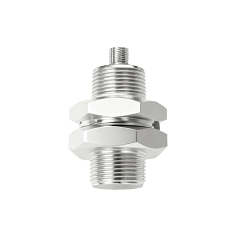
The output circuitry of a DC proximity switch is classified as either sourcing (PNP) or sinking (NPN). This classification defines the current flow path relative to the load and controller input. A sourcing (PNP) sensor switches the positive voltage to the load. In a typical PNP wiring diagram, the brown wire connects to the DC positive supply (e.g., +24V), the blue wire to the DC negative (0V), and the black output wire connects to one terminal of the load (e.g., a PLC digital input). The other terminal of the load is then connected to 0V. When the sensor detects an object, it sources current from the supply, through the sensor's output transistor, to the load. Conversely, a sinking (NPN) sensor switches the negative or ground path. Here, the black output wire connects to the load, and the other load terminal connects to +V. When activated, it allows current to sink from the load, through the sensor, to ground. The choice between PNP and NPN is crucial and must align with the input circuit design of the programmable logic controller (PLC) or relay module being used.
Detailed Wiring Diagram Analysis
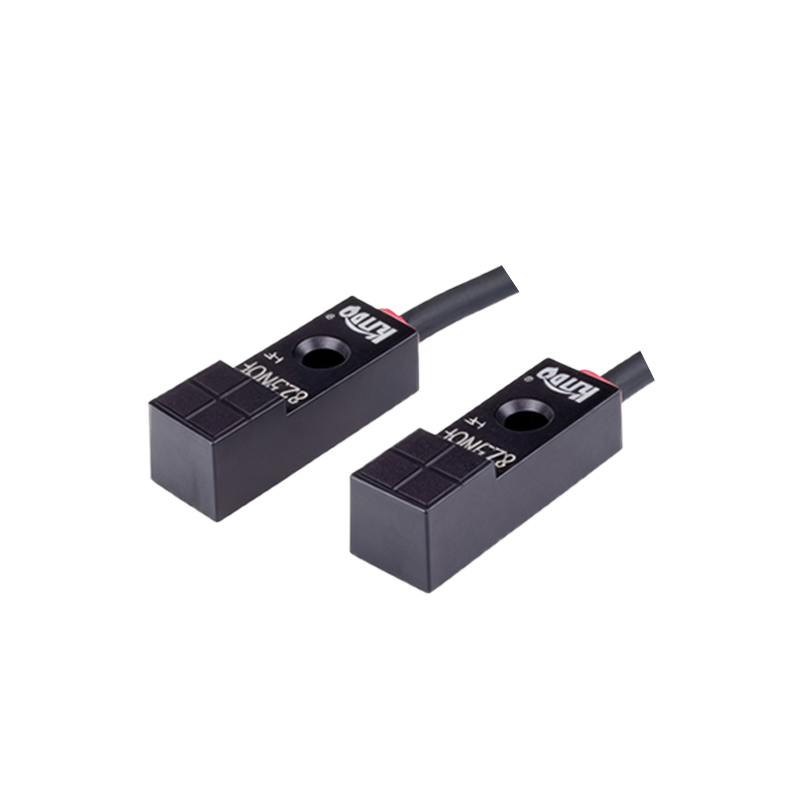
Examining a practical wiring diagram for a 3-wire DC inductive proximity switch in a PNP configuration reveals a clear circuit path. The power supply, often 10-30V DC, has its positive pole linked to the brown wire. The negative pole connects to the blue wire and also to one side of the load (e.g., terminal S/S on a PLC input card configured for PNP). The sensor's black output wire is connected directly to the specific PLC input channel (e.g., X0). When a metal object enters the sensing field, the sensor's internal solid-state switch closes the circuit between the brown and black wires. This action applies the positive supply voltage to the PLC input, signaling a HIGH or 'ON' state. The diagram must also include protective elements, such as a fuse on the supply line and, in some cases, a flyback diode across an inductive load (like a relay coil) to suppress voltage spikes. For AC sensors, wiring involves connecting the brown wire to the live AC terminal, blue to neutral, and the output in series with the load to complete the AC circuit.
Installation Best Practices and Safety
Proper installation extends beyond correct wire connections. Mounting the sensor securely with appropriate brackets ensures stable sensing distance. Maintain adequate clearance between the sensor face and metal mounting surfaces to prevent false triggering, especially for inductive types. Cable routing is critical; sensor cables should be kept separate from high-voltage power cables and motor leads to minimize electromagnetic interference (EMI), which can cause erratic behavior. Using shielded cables with the shield grounded at only one end (typically the control panel end) is a highly recommended practice for noise immunity.