Understanding Photoelectric Sensor Wiring Fundamentals
Photoelectric sensors are pivotal components in industrial automation, enabling non-contact detection of objects through light beams. A common query among engineers and technicians is: "How many wires do most photoelectric sensors have?" The answer typically revolves around three to four wires, though this can vary based on the sensor's function and output type. Most standard DC-powered photoelectric sensors feature three wires: one for power supply (positive), one for ground (negative), and one for the output signal. This configuration is prevalent in sensors with a single switching output, such as NPN (sinking) or PNP (sourcing) transistor outputs. For instance, in a three-wire DC sensor, the brown wire is usually connected to the positive voltage (e.g., +24V DC), the blue wire to the ground (0V), and the black wire to the output signal that switches based on detection. This setup ensures efficient operation in control systems, allowing the sensor to transmit detection data to programmable logic controllers (PLCs) or other devices. Understanding this wiring is crucial for proper installation and troubleshooting in applications like conveyor systems, packaging machinery, and safety barriers.
Common Wire Configurations and Their Purposes
Expanding beyond the basic three-wire setup, many photoelectric sensors incorporate four wires to enhance functionality. A four-wire sensor often includes two output wires instead of one, enabling dual outputs like a normally open (NO) and a normally closed (NC) contact. This provides flexibility in control circuits, allowing users to choose between different logic states based on application needs. For example, in a four-wire DC sensor, the wiring might consist of brown for positive voltage, blue for ground, black for the NO output, and white for the NC output. Additionally, some sensors feature extra wires for diagnostic functions, such as a stability indicator or a teach-in mode for adjusting sensitivity. In AC-powered sensors, wiring can differ, with two wires for power (e.g., line and neutral) and one or two for outputs, but these are less common in modern industrial settings due to the prevalence of DC systems. It's essential to consult the sensor's datasheet, as wire colors and functions can vary by manufacturer—brown and blue are standard for power per IEC 60947-5-2, but outputs may use black, white, or gray. This variability underscores the importance of verifying wiring diagrams to prevent errors in connectivity.
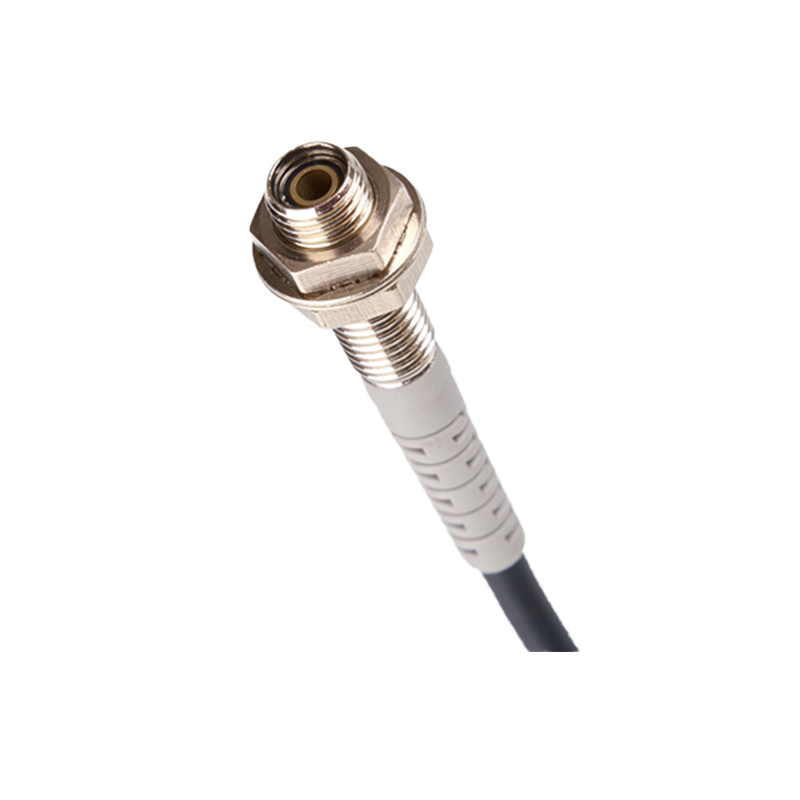
Factors Influencing Wire Count in Sensor Design
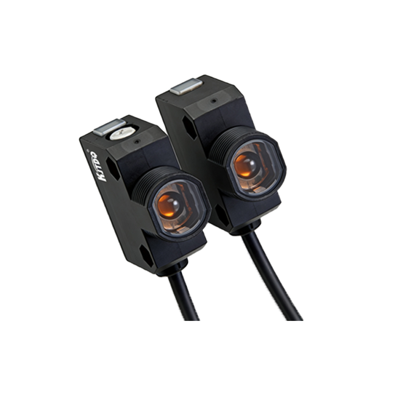
The number of wires in a photoelectric sensor is not arbitrary; it's dictated by the sensor's operational requirements and features. Key factors include the output type, power supply, and additional functionalities. For basic switching, a three-wire setup suffices, but sensors with analog outputs (e.g., 0-10V or 4-20mA) may require more wires to transmit continuous data. Similarly, sensors with built-in timers, counters, or communication interfaces (like IO-Link) often have additional wires for data transmission and configuration. In advanced models, you might find five or more wires to support features like push-pull outputs, which combine NPN and PNP outputs in one device, or for separate wires for power and signal grounding to reduce electrical noise. Environmental considerations also play a role: sensors used in harsh conditions might include shielded wires or extra conductors for diagnostics to ensure reliability. Ultimately, the wire count reflects the sensor's complexity—simple presence detection typically uses fewer wires, while smart sensors with enhanced capabilities require more. Engineers must balance cost, space, and functionality when selecting sensors, as more wires can mean higher installation complexity but greater control.
Practical Wiring Tips for Installation and Maintenance
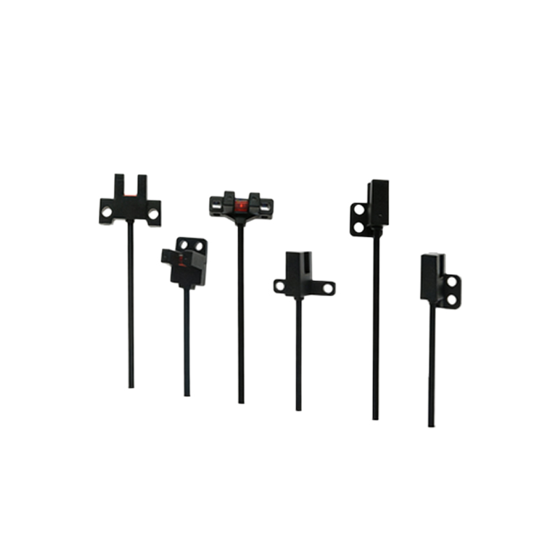
To ensure optimal performance, follow best practices when wiring photoelectric sensors. First, always disconnect power before installation to prevent electrical hazards. Use the correct wire gauges as specified in the manual, typically 18-22 AWG for most industrial sensors, to avoid voltage drops or overheating. For three-wire sensors, connect the brown wire to the positive DC supply (e.g., +24V), the blue wire to the negative or ground, and the output wire (often black) to the load, such as a PLC input module. In four-wire sensors, double-check the output assignments—for instance, a black wire might be NO, and a white wire NC, which can be wired in parallel or series depending on the circuit logic. Employ proper cable management, such as conduits or cable ties, to protect wires from mechanical damage and electromagnetic interference. Regularly inspect connections for corrosion or looseness, especially in humid or vibrating environments. If a sensor malfunctions, use a multimeter to test voltage at the power wires and output signals; incorrect wiring is a common cause of failure. By adhering to these guidelines, you can extend sensor lifespan and maintain system efficiency in automation projects.
Conclusion: Choosing the Right Sensor for Your Application
In summary, most photoelectric sensors have three to four wires, with three-wire models being the industry standard for basic DC switching applications. The wire count increases with added features like dual outputs, analog signals, or smart communication. When selecting a sensor, consider your application's needs: a simple three-wire sensor may suffice for object detection on a production line, while a four-wire or multi-wire sensor offers versatility for complex control tasks. Always refer to manufacturer documentation for precise wiring instructions, as standards can vary. By understanding these wiring principles, engineers can deploy photoelectric sensors effectively, enhancing automation systems' reliability and productivity. As technology evolves, sensors may integrate wireless options, but wired configurations remain dominant for their stability in industrial environments.