Understanding Inductive Proximity Sensors
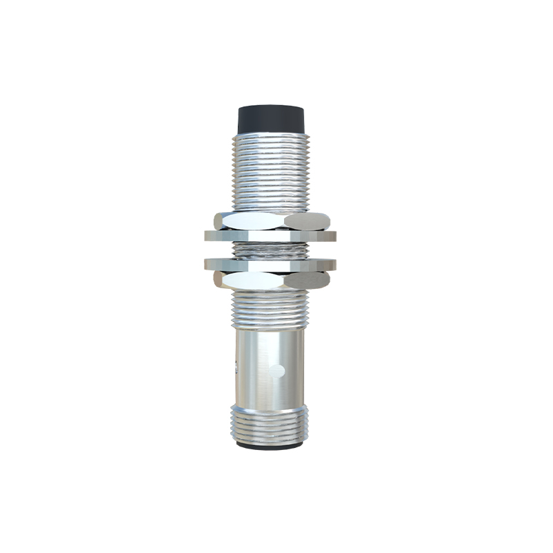
Inductive proximity sensors are non-contact devices used to detect metallic objects by generating an electromagnetic field. They operate on the principle of electromagnetic induction, where a coil and oscillator create a field that, when disturbed by a metal target, triggers a change in output. These sensors are widely employed in industrial automation, machinery, and safety systems due to their reliability, durability, and ability to function in harsh environments. Common applications include position sensing, object counting, and limit switching. Understanding their working mechanism is essential for proper installation, as factors like sensing range, target material, and environmental conditions can impact performance. Typically, inductive sensors detect ferrous metals like steel at greater distances compared to non-ferrous metals such as aluminum or copper.
Pre-Installation Planning and Considerations
Before installing an inductive proximity sensor, thorough planning ensures optimal functionality and longevity. Start by reviewing the sensor's datasheet for specifications such as sensing distance, voltage rating, output type (e.g., NPN or PNP), and housing material. Select a sensor suitable for the operating environment—consider factors like temperature extremes, humidity, dust, and potential exposure to chemicals or oils. Ensure the target object is metallic and within the specified sensing range; for example, standard sensors may have ranges from 1 to 40 mm. Verify the electrical requirements, including power supply compatibility (commonly 10-30 V DC) and load current, to prevent damage. Additionally, plan the mounting location to avoid interference from other electromagnetic sources, such as motors or transformers, which could cause false triggers.
Mounting and Alignment Procedures
Proper mounting is critical for accurate detection. Mount the sensor securely using brackets or threaded housings, ensuring it is fixed in place to prevent vibration-induced misalignment. For cylindrical sensors, use lock nuts to stabilize the position. Align the sensor face parallel to the target surface for maximum sensitivity; angular misalignment can reduce the effective sensing distance. Maintain the recommended gap between the sensor and target, typically 0.1 to 0.5 times the nominal sensing distance, to account for tolerances and thermal expansion. In applications involving multiple sensors, space them adequately to avoid mutual interference—a general rule is to keep distances at least twice the sensor diameter apart. For flush-mounted sensors, ensure the surrounding material is non-metallic to prevent shielding effects, while non-flush types can be mounted with metal nearby but may require adjustment.
Electrical Wiring and Connection Guidelines
Correct wiring ensures safe and reliable operation. Begin by disconnecting power to the circuit to prevent electrical hazards. Refer to the sensor's wiring diagram: typically, inductive sensors have three wires—brown (power positive), blue (power negative or ground), and black (output signal). For DC sensors, connect the brown wire to the positive supply and blue to negative; for AC versions, follow manufacturer instructions as wiring may differ. Use shielded cables in environments with high electrical noise to minimize interference, and ground the shield at one end. Ensure connections are tight and insulated to avoid short circuits. If using a programmable logic controller (PLC) or relay, match the sensor output type (e.g., sinking or sourcing) to the input requirements. Test the wiring with a multimeter to verify voltage levels before powering the system fully.
Testing and Calibration Steps
After installation, testing validates sensor performance. Power the system and observe the sensor's indicator LED, which usually lights up when a target is detected. Introduce a metal object within the sensing range and check for consistent output activation. Use a oscilloscope or diagnostic tool if available to monitor signal stability, especially in high-speed applications. Calibrate the sensing distance if the sensor allows adjustment—some models feature potentiometers for fine-tuning sensitivity. Ensure the sensor responds only to intended targets; adjust the mounting or sensitivity to avoid false triggers from nearby metal objects or environmental noise. Perform long-term tests under normal operating conditions to confirm reliability, and document settings for future maintenance.
Maintenance and Troubleshooting Tips
Regular maintenance extends sensor life and prevents downtime. Periodically inspect the sensor for physical damage, corrosion, or contamination; clean the face with a soft cloth to remove dirt or metal shavings that could affect performance. Check wiring connections for looseness or wear, and replace cables if insulation is compromised. Common issues include no output signal, intermittent detection, or reduced sensing range. Troubleshoot by verifying power supply voltage, testing with different targets, and ensuring no electromagnetic interference. If problems persist, consult the manufacturer's guidelines or replace the sensor. Keep spare sensors on hand for critical applications to minimize operational disruptions.