Understanding Photoelectric Sensor Series Connection Fundamentals
Connecting photoelectric sensors in series is a common practice in industrial control panels and machine safety circuits. This configuration involves wiring multiple sensors so that their output signals are logically combined, typically to create a single, overarching control signal. The primary purpose is to establish a condition where all sensors in the series must be in a specific state—often the "normal" or "clear" state—for the final output to be active. If any one sensor in the chain detects an object or a fault, it breaks the circuit, changing the final output state. This method is fundamentally different from parallel connections, where any sensor can trigger an action. Series wiring is inherently a logical AND function; Sensor A AND Sensor B AND Sensor C must be satisfied for the system to proceed. This is crucial for applications like multi-point safety guarding, sequential process verification, or ensuring a clear path along a conveyor line.
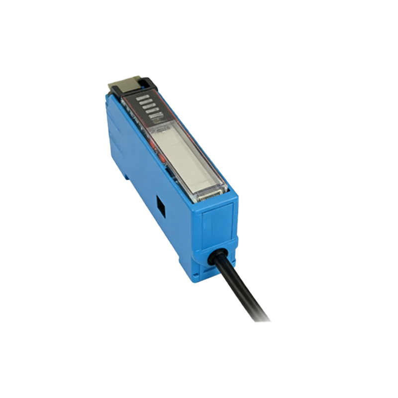
Key Considerations Before Wiring Sensors in Series
Before implementing a series connection, several critical factors must be evaluated to ensure reliability and safety. First, verify the sensor output type. For DC sensors, the most common method involves connecting the load (like a PLC input or relay coil) in series with the sensor's switched output lines. You must confirm whether your sensors provide a Normally Open (NO) or Normally Closed (NC) contact in their output stage. For safety circuits, NC contacts (also known as "safe" contacts) are often preferred because a wire break will mimic an object detection, causing a safe shutdown. Second, check voltage and current ratings. The cumulative voltage drop across each sensor's output transistor or relay must be considered to ensure the final load receives sufficient voltage to operate. Exceeding the maximum current rating of any single sensor's output can lead to failure. Third, consider diagnostics. A simple series circuit makes it difficult to pinpoint which specific sensor triggered a shutdown without additional monitoring modules or networked sensors.
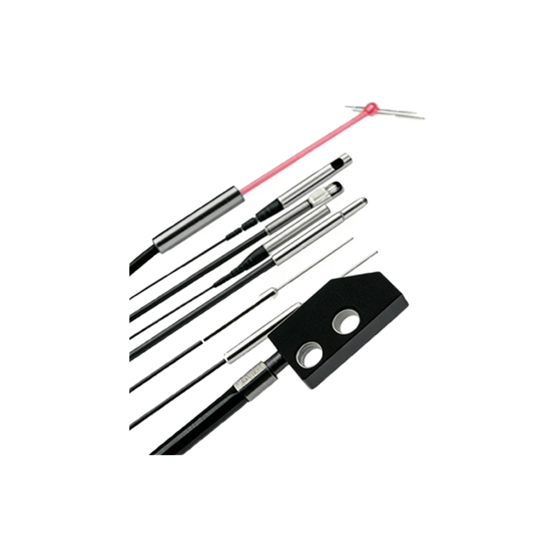
Step-by-Step Wiring Procedure for DC 3-Wire Sensors
For the ubiquitous DC 3-wire PNP (sourcing) or NPN (sinking) sensors, the series connection process is straightforward. Let's assume we are connecting two PNP sensors with NO outputs. Begin by connecting the positive supply voltage (e.g., +24VDC) to the brown wire (V+) of the first sensor. Connect the blue wire (0V or common) of the first sensor to the system power supply's negative terminal. The black wire (signal output) of the first sensor is not connected directly to the load. Instead, connect it to the brown wire (V+) of the second sensor. Then, connect the blue wire of the second sensor to the system common (0V). Finally, connect the black output wire of the second sensor to one terminal of your load (e.g., a PLC digital input). The other terminal of the load is connected to the system common (0V). In this configuration, both sensors must have their outputs active (switched on) to provide the complete path for current to flow from the supply, through both sensors, into the load, and back to common. For NPN sensors, the logic is similar but with the load connected between the positive supply and the sensor chain.
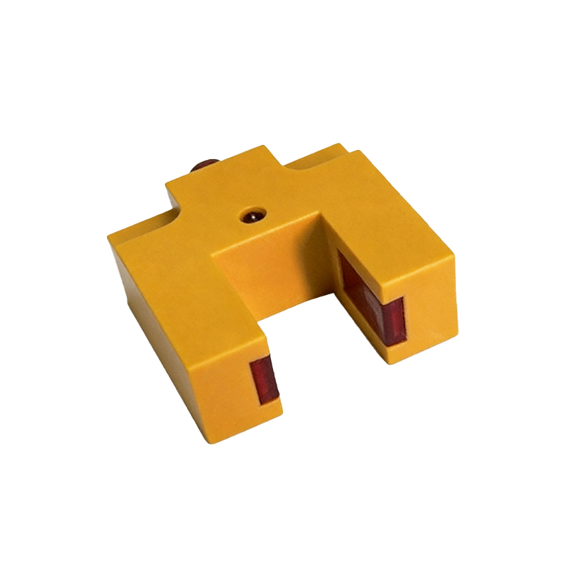
Implementing Series Connections with Relay Outputs
Photoelectric sensors with built-in electromechanical or solid-state relay outputs are well-suited for series connections, especially in AC circuits or when isolating different voltage domains. The procedure involves connecting the switched output contacts in series. For example, with two sensors having SPDT relay outputs, you would wire the common (C) terminal of the first sensor's relay to one side of the power source. The normally open (NO) terminal of the first relay is then connected to the common (C) terminal of the second sensor's relay. Finally, the normally open (NO) terminal of the second relay is connected to one side of the load. The other side of the load connects back to the other side of the power source. This creates a classic series switch circuit. The advantage of this method is its simplicity and high current-carrying capacity. However, the mechanical life of relays and potential contact bounce should be considered for high-speed applications.
Critical Applications and Safety Implications
Series connections are paramount in safety-related systems, such as perimeter guarding on robotic cells or access gates on machinery. In these applications, multiple safety interlock switches or light curtains are wired in series to form a safety chain. Any breach opens the chain, immediately de-energizing a safety relay or controller, which in turn removes motive power from the machine. It is vital to follow applicable standards like ISO 13849-1 or IEC 62061 when designing safety circuits. For non-safety critical applications, series wiring is used for process logic. For instance, on a packaging line, a series of sensors might verify that a box is present, the lid is closed, and a label is applied before allowing the box to proceed to the sealing station. This ensures all process conditions are met sequentially.
Troubleshooting Common Issues in Series Circuits
Diagnosing faults in a series-connected sensor string can be challenging. A single faulty sensor or a broken wire will cause the entire circuit to appear inactive. A systematic approach is required. Use a digital multimeter to check for voltage at key points. Start by verifying power is present at the first sensor. Then, check if the output of the first sensor becomes active when its sensing condition is met. If it does, move to the input power terminal of the second sensor. Continue this process down the chain until you find the point where the voltage is missing. Another common issue is insufficient voltage at the load due to cumulative voltage drops, especially with long wire runs or many sensors in series. Ensure the voltage measured directly across the load terminals is within its operational specification when all sensors are active. For complex systems, consider using sensors with diagnostic outputs or integrating them into a network (like IO-Link) which provides individual sensor status while maintaining the series logic at the controller level.