Introduction to Inductive Proximity Sensors
Inductive proximity sensors are fundamental components in industrial automation, renowned for their non-contact detection of metallic objects. Operating on the principle of electromagnetic induction, these sensors generate an oscillating electromagnetic field from a coil. When a metallic target enters this field, eddy currents are induced on the target's surface, causing a change in the oscillation amplitude. This change is detected by the sensor's internal circuitry, which subsequently triggers a switching action. The reliability, long operational life, and resistance to harsh environments make them indispensable in applications ranging from machine tools and material handling to automotive assembly lines. The core of their output functionality, however, is defined by their switching configuration, primarily categorized as NPN or PNP, which dictates how they interface with control systems like PLCs.
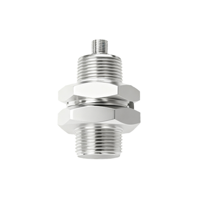
Defining the NPN Output Configuration
The term "NPN" refers to the type of bipolar junction transistor (BJT) used in the sensor's output switching circuit. In an NPN inductive proximity sensor, the output transistor is an NPN type. To understand its operation, one must visualize the three terminals of an NPN transistor: the Emitter (E), the Base (B), and the Collector (C). In a typical sensor wiring scheme, the Emitter is connected to the common negative or 0V DC supply line (often labeled as GND or -). The load (e.g., a PLC input module, relay coil, or indicator lamp) is connected between the sensor's output signal wire (from the Collector) and the positive supply voltage (+V). In its normal state (no target detected), the transistor is off, acting as an open switch. No current flows from the Collector to the Emitter, so the output signal line remains at a high potential (close to +V).
Switching Behavior: Sinking Current
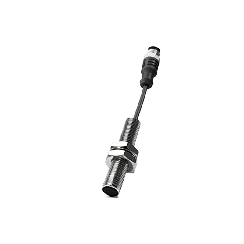
The defining characteristic of an NPN output is its "sinking" behavior. When a valid metallic target enters the sensor's sensing range, the internal circuit activates, biasing the NPN transistor into saturation. This turns the transistor "on," effectively closing the switch between the Collector and Emitter. In this state, the output terminal (Collector) is pulled down to a low voltage (near 0V or GND). Current now flows from the positive supply (+V), through the connected load, into the sensor's output terminal (Collector), and sinks down through the transistor to the common negative (Emitter to GND). Thus, an NPN sensor is said to provide a "sinking" output or an "active-low" signal. It acts as a path to ground for the current flowing through the load.
Wiring and Practical Connection Examples
Correct wiring is crucial for system functionality and safety. A standard three-wire DC inductive proximity sensor with an NPN output will have wires for Brown (+V), Blue (0V/GND), and Black (Output). The Brown wire connects to the positive DC supply (e.g., +24V). The Blue wire connects to the power supply's 0V or negative terminal. The Black output wire connects to one side of the load. The other side of the load is then connected to the positive supply (+V). For instance, when connecting to a PLC digital input card, the Black wire from the sensor would connect to the specific input terminal (e.g., I0.0). The common terminal of that PLC input group, which is internally connected to +24V for a sinking-type input card, would connect to the positive supply. This creates the complete circuit: +24V -> PLC internal circuit -> Input I0.0 -> Sensor Black wire -> Internal NPN transistor -> Sensor Blue wire -> 0V.
NPN vs. PNP: A Critical Distinction
The counterpart to NPN is the PNP output configuration. This distinction is one of the most common sources of wiring errors. While an NPN sensor sinks current to ground, a PNP sensor sources current from the positive supply. In a PNP sensor, the load is connected between the output and GND. When active, the PNP transistor switches, providing a positive voltage (+V) to the load. A simple mnemonic is "NPN: Negative-switched Positive," indicating it switches the negative side. The choice between NPN and PNP is primarily dictated by the electrical design of the control system. Many Asian and European systems traditionally favor PNP sourcing inputs, while NPN sinking sensors are prevalent in other regions and are commonly required for compatibility with certain PLC models, especially those from Japan.
Application Considerations and Selection Criteria
Select