Understanding Photoelectric Sensor Fundamentals
Before initiating the CAD drawing process, a clear understanding of the photoelectric sensor's components is essential. A typical photoelectric sensor consists of a light emitter (usually an LED or laser diode), a light receiver (phototransistor or photodiode), a housing, mounting brackets, electrical connection ports, and often alignment indicators or status LEDs. Engineers must refer to the specific manufacturer's datasheet for precise dimensional tolerances, mechanical outlines, and connection specifications. This foundational knowledge ensures the CAD model accurately reflects the physical device's form, fit, and function, which is critical for integration into larger electrical or mechanical assemblies.
Setting Up Your CAD Software Environment
Begin by launching your preferred CAD software, such as AutoCAD, SolidWorks, or Fusion 360. Create a new part file and set the units to millimeters or inches, consistent with the sensor's datasheet. Configure appropriate layers for different elements: one for the main housing outline, another for mounting features, and separate layers for electrical connections and annotation. Setting up a grid and snap function aligned with common measurement increments can significantly enhance drawing precision. Establishing this organized workspace from the outset streamlines the drafting process and facilitates future modifications.
Creating the Basic Housing Outline
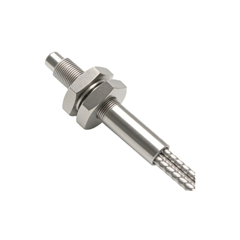
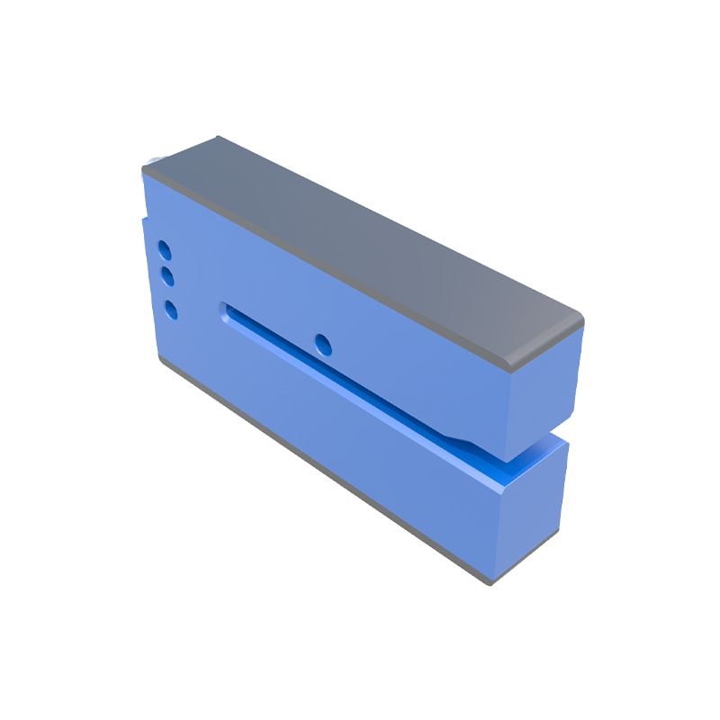
Using the line, rectangle, and circle tools, start by drafting the primary housing profile based on the sensor's maximum length, width, and height dimensions. Most industrial photoelectric sensors feature a rectangular or cylindrical body. For a rectangular type, use the rectangle command, inputting the exact length and width. For cylindrical sensors, use the circle command for the diameter. Employ the extrude or press/pull command to give the 2D profile its third-dimensional height. This extruded shape forms the core solid body of the sensor housing. Pay close attention to any tapered or rounded edges, using fillet and chamfer commands to replicate these details accurately.
Detailing Mounting Features and Brackets
Photoelectric sensors are typically mounted via threaded holes, slots, or dedicated mounting brackets. Locate the position of these features from the datasheet's mechanical drawing. Use the circle tool to draw the diameter of mounting holes on the relevant faces of the housing. Then, use the extrude cut or hole command to create the holes. For bracket arms, sketch the bracket profile on the appropriate plane relative to the main body and extrude it. Ensure that hole spacing and bracket dimensions are exact to guarantee proper mechanical fixation in the final assembly. Adding thread details, if specified, enhances the model's realism for advanced manufacturing drawings.
Modeling the Optical Components
The emitter and receiver lenses are critical functional elements. On the respective faces of the housing, draw concentric circles representing the protective lens cover and the internal lens aperture. These are usually smaller circular features. Slightly recess or protrude these lens areas from the main housing face using a slight extrude or cut to differentiate them. While the internal electronics are not modeled, indicating the lens location and type (through-beam, retro-reflective, or diffuse) through annotation or a simple schematic on a separate layer can be valuable for instructional or presentation drawings.
Adding Electrical Connections and Ports
The electrical interface, often a pre-wired cable or a connector port like an M8 or M12, must be accurately represented. For a connector, model the port's cylindrical shape on the housing using the circle and extrude commands. Include key features like notches or locking threads. For cable outlet models, draw the cable gland area and use a sweep command to create a simplified representation of the cable extending from the housing. Create separate connection point sketches or annotations labeling the pin assignments (e.g., V+, V-, Output) according to the datasheet, which is crucial for the subsequent electrical schematic design.
Applying Annotations and Dimensions
A professional engineering drawing is incomplete without comprehensive annotation. Switch to a layout or drawing sheet to create orthographic views (front, top, side, isometric) of your 3D model. Use the dimension tool to add all critical measurements: overall dimensions, mounting hole centers, lens diameters, and port locations. Add text notes for material specifications (e.g., "Housing: PBT Plastic"), operating voltage, and output type (PNP/NPN). Proper dimensioning ensures the drawing communicates all necessary information for procurement, machining of mounting panels, or system integration without ambiguity.
Finalizing and Exporting the Drawing File
Conduct a final review against the manufacturer's datasheet to verify accuracy. Check for any missing features or incorrect dimensions. Perform a basic interference check if the sensor is part of a larger assembly file. Once validated, save the native CAD file for future edits. Then, export the drawing into the required formats for sharing or documentation. Common formats include PDF for universal viewing, DWG or DXF for collaboration with other CAD platforms, and STEP or IGES for 3D model exchange with colleagues in mechanical design. A well-drawn CAD model of a photoelectric sensor serves as a reliable digital twin for the entire design lifecycle.