Introduction to Proximity Sensing Technology
Proximity sensor switches are fundamental components in modern industrial automation and control systems. These non-contact sensors detect the presence or absence of an object within a specified range without any physical contact. The core principle relies on changes in an electromagnetic field, capacitance, or light beam. The schematic diagram of a proximity switch is the blueprint that defines its electrical behavior, interconnection with other components, and overall functionality within a circuit. Understanding this schematic is crucial for electrical engineers involved in system design, troubleshooting, and maintenance. It translates the physical sensing action into a usable electrical signal, typically a switched output that can interface with programmable logic controllers (PLCs), relays, or other control devices. The schematic provides insights into the sensor's power requirements, output type (NPN sinking or PNP sourcing), and connection methodology.
Core Components in a Typical Schematic
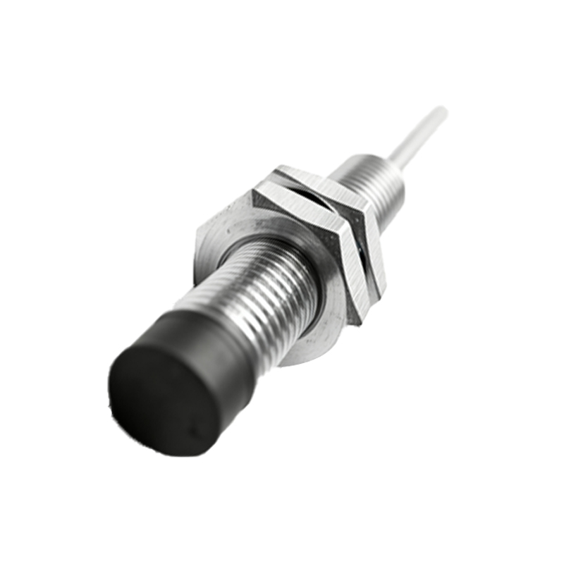
A standard inductive proximity sensor schematic, one of the most common types, reveals several key internal blocks. The oscillator circuit is the heart, generating a high-frequency electromagnetic field from the sensing face coil. When a metallic target enters this field, eddy currents are induced, causing a dampening or amplitude change in the oscillator's signal. This change is detected by the threshold detector or trigger circuit. The signal then passes to the output driver stage. For a 3-wire DC sensor, the schematic clearly shows three terminals: V+ (brown wire, typically 10-30V DC), V- (blue wire, 0V common), and the output signal wire (black or white). The output switching element, a transistor (either NPN or PNP), is depicted in this section. Protection components like reverse polarity diodes, surge suppression circuits, and short-circuit protection are also integrated into the schematic to ensure robustness in harsh industrial environments.
Analyzing Output Configuration: NPN vs. PNP
The schematic is indispensable for distinguishing between NPN (sinking) and PNP (sourcing) output configurations, a critical selection parameter. In an NPN proximity switch schematic, the output transistor is an NPN type. Its emitter is connected to the negative supply (V- or 0V). The load (e.g., a PLC input) is connected between the sensor's output wire (collector) and the positive supply (V+). When activated, the NPN transistor sinks current from the load to ground, completing the circuit. Conversely, a PNP sensor schematic shows a PNP transistor with its emitter tied to V+. The load is connected between the output wire (collector) and V-. When activated, the PNP transistor sources current from V+ through the load to ground. The schematic symbols make this distinction immediately clear, preventing wiring errors that could lead to system malfunctions.
Interfacing with Control Systems
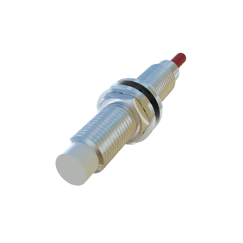
The schematic extends beyond the sensor itself to show proper interfacing with external control systems. For connecting to a PLC digital input module, the diagram illustrates the complete current path. It specifies the necessity of a pull-up or pull-down resistor in certain configurations to ensure a defined logic state when the sensor is off. The schematic also indicates the typical connection for the indicator LED, which is in parallel with the output switching element, providing visual status feedback. For two-wire AC sensors, the schematic resembles that of a standard switch in series with the load and the AC supply, but includes internal rectification and stabilization circuitry to power the electronic components. Understanding these interface details from the schematic allows engineers to design reliable and noise-immune signal chains.
Capacitive and Ultrasonic Sensor Schematics
While inductive sensors detect metals, capacitive proximity switches sense both metallic and non-metallic materials. Their schematic reveals a different oscillator circuit where the sensing face forms one plate of a capacitor. The target alters the dielectric constant, changing the capacitance and thus the oscillator frequency, which is detected similarly. The output stage remains comparable to inductive types. Ultrasonic sensor schematics are more complex, showing separate blocks for the piezoelectric transmitter (driven by a pulse generator) and receiver. A timing circuit or microcontroller measures the time-of-flight of the reflected sound wave. The analog echo signal is amplified, filtered, and processed to generate a digital output signal. These schematics highlight the specialized signal conditioning required for different sensing modalities.
Practical Considerations from Schematic Analysis
A thorough review of the proximity switch schematic provides practical engineering insights. It specifies the voltage operating range and current consumption. The presence of a hysteresis circuit in the detection stage explains the difference between the operating point and release point, preventing output chatter. The schematic shows the connection for the sensing distance adjustment potentiometer, if available. It also reveals the wiring for sensors with complementary outputs (NO and NC