Introduction to Three-Wire Photoelectric Proximity Sensors
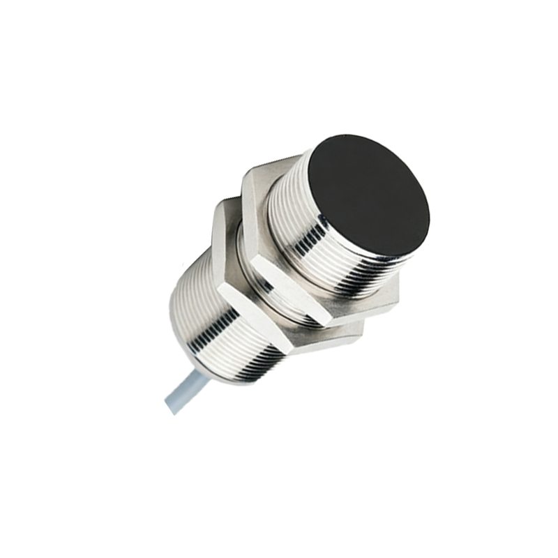
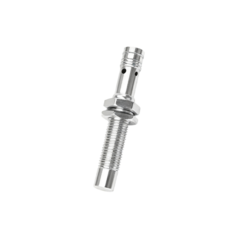
The three-wire photoelectric proximity sensor represents a fundamental and widely adopted component in industrial automation. Unlike mechanical limit switches, these sensors operate without physical contact, detecting the presence or absence of objects through modulated light beams. The "three-wire" designation specifically refers to the power supply configuration: typically comprising a positive voltage wire (brown or red), a negative or ground wire (blue or black), and a signal output wire (black, white, or another color). This design provides a distinct advantage over two-wire models by offering a physically separate output circuit, which allows for lower leakage current, higher switching speeds, and compatibility with a broader range of programmable logic controllers (PLCs) and control systems. The core sensing element, or "photoelectric body," houses the optical components and electronics that define the sensor's performance characteristics.
Core Operating Principles and Sensing Modes
The functionality of the photoelectric body hinges on the interaction between an emitted light source and a receiver. Common light sources include Light Emitting Diodes (LEDs) emitting visible red, infrared, or laser light. The receiver is typically a phototransistor or photodiode. Three primary sensing modes are employed. The through-beam (or opposed) mode uses separate units for the emitter and receiver, offering the longest sensing ranges and highest reliability, as an object is detected when it interrupts the beam. The retro-reflective mode combines the emitter and receiver in a single housing, using a reflector to bounce the light back; detection occurs when the beam is blocked. Finally, the diffuse (or proximity) mode also houses both elements together but detects light reflected directly off the target object itself. This mode is highly versatile but has a shorter range and can be influenced by the object's color and surface texture.
Electrical Characteristics and Wiring Configurations
Understanding the electrical interface is critical for proper integration. The three wires provide a straightforward connection. The power supply, usually 10-30V DC, is connected across the positive and negative terminals. The output wire provides the switching signal. These sensors are classified as either NPN (sinking) or PNP (sourcing) outputs, a crucial distinction. An NPN sensor switches the negative (0V) side of the load to the common negative, while a PNP sensor switches the positive voltage to the load. The load (e.g., a PLC input, relay, or indicator) is connected between the output wire and the opposite supply rail. Additionally, many modern three-wire sensors feature selectable light-on/dark-on operation, allowing the output to be active either when the light beam is received (light-on) or when it is interrupted (dark-on), providing flexibility for different application logic.
Key Performance Specifications and Selection Criteria
Selecting the appropriate sensor requires careful analysis of several specifications tied to the photoelectric body. Sensing range is the maximum reliable distance for object detection, varying significantly between sensing modes. Response time, often in milliseconds or microseconds, dictates how quickly the output switches after a detection event, critical for high-speed applications. Repeatability defines the precision of the detection point. Environmental factors are paramount: the housing material (often metal or high-grade plastic) and Ingress Protection (IP) rating determine resistance to dust, water, oils, and chemicals. Operating temperature range must suit the installation environment. Furthermore, features like background suppression (for ignoring distant objects), fixed or adjustable sensitivity, and built-in diagnostics (like stability or function indicators) enhance performance in complex settings.
Common Industrial Applications and Integration
The robustness and reliability of three-wire photoelectric sensors make them indispensable across numerous sectors. In packaging and material handling, they count products on conveyors, detect jams, and control filling levels. In automotive assembly, they verify part presence, position robots, and inspect for correct component installation. Within electronics manufacturing, they ensure precise placement of tiny components on printed circuit boards. They are also extensively used for edge detection in web guiding systems, door control for safety, and palletizing/depalletizing operations. Successful integration involves not just correct wiring but also optimal mounting, alignment, and consideration of environmental interferences such as ambient light, vibration, and airborne contaminants that could affect the optical path.
Installation Best Practices and Troubleshooting Guidelines
Proper installation is key to long-term, trouble-free operation. Ensure the sensor is securely mounted to minimize vibration-induced misalignment. For through-beam and retro-reflective types, precise alignment between the emitter, receiver, and/or reflector is essential; built-in alignment indicators are highly beneficial. Protect the lens