Introduction to Proximity Sensor Open Circuits
An open circuit in a proximity sensor is a common yet critical fault condition that can bring automated processes to a standstill. Essentially, it means the electrical path within the sensor or its connecting wiring is broken, preventing the flow of current necessary for the sensor to signal the detection of a target. Unlike a short circuit, an open circuit results in a complete loss of signal. For inductive and capacitive proximity sensors, this typically manifests as the sensor failing to switch its output state regardless of target presence. For analog or IO-Link sensors, it may result in a loss of communication or a fault code at the controller. Understanding the root causes is the first step in effective troubleshooting and minimizing costly downtime in industrial settings.
Internal Component Failure
The sensor's internal electronics are susceptible to several failure modes leading to an open circuit. The most frequent culprit is the failure of the output switching device, such as a transistor in DC sensors or a triac in AC sensors. These semiconductor components can be damaged by voltage transients, often induced by inductive loads like solenoids or relays without proper suppression. Overcurrent conditions, though less common than in short circuits, can also thermally damage these components, creating an open path. Additionally, failure of the oscillator circuit in inductive sensors, or degradation of capacitors and resistors on the printed circuit board (PCB) due to heat or aging, can interrupt the internal signal chain, resulting in an open circuit fault.
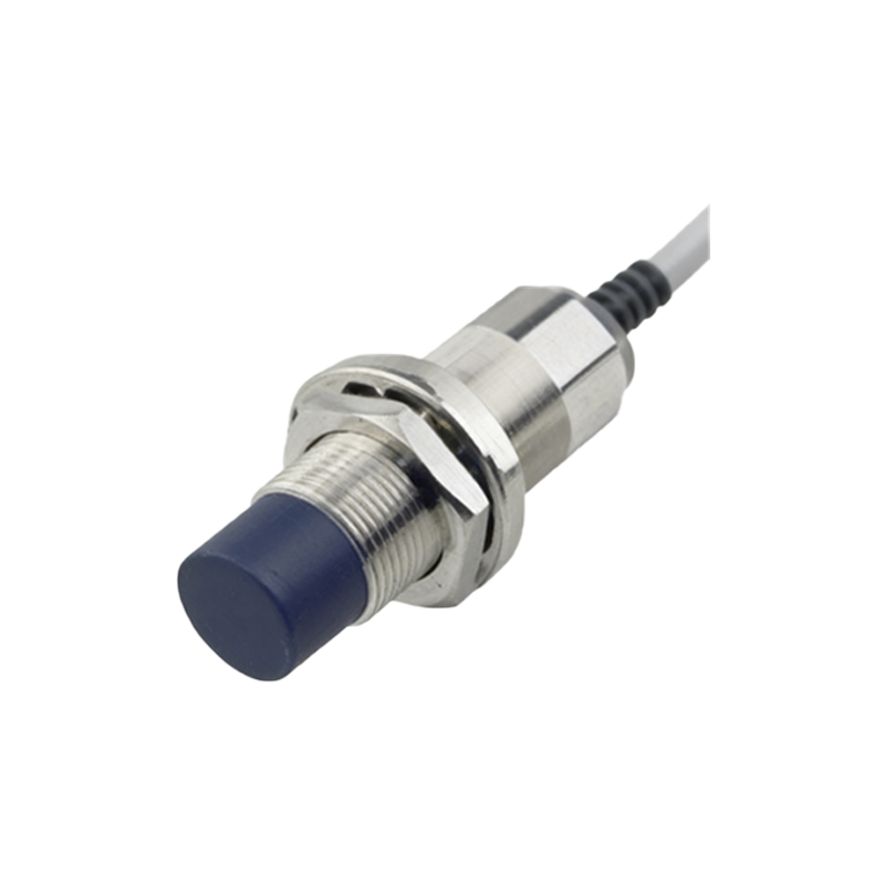
Wire and Cable Damage
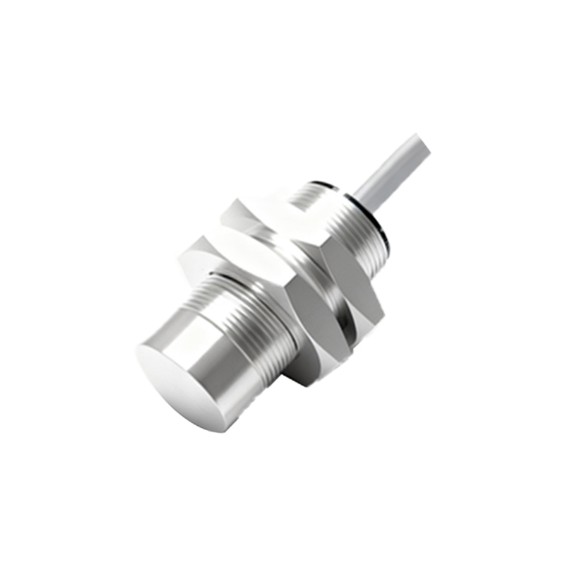
Physical damage to the sensor's cable or internal wiring is a leading cause of open circuits in harsh industrial environments. Constant flexing, tension, or crushing can break the fine internal conductors. Cable jackets can be cut by sharp edges, abraded by repeated motion, or chewed by rodents. Even if the insulation remains intact, the copper strands inside can fracture, especially at stress points like the cable entry into the sensor housing or at terminal block connections. Vibration is a silent enemy that can work-harden wires and cause them to snap. For sensors with quick-disconnect (M12, M8) connectors, bent pins, corrosion, or loose connections within the connector body can create an intermittent or permanent open circuit.
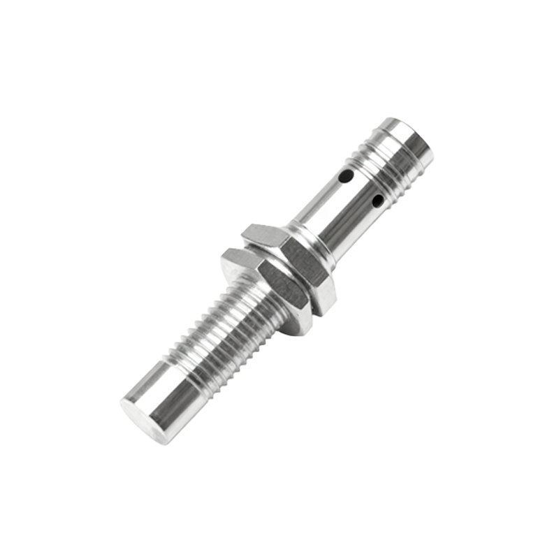
Poor Electrical Connections
Loose, corroded, or improperly made electrical connections are a prime source of open circuits. At the sensor's terminal block, wires that are not securely tightened can vibrate loose, breaking contact. Using ferrules on stranded wire is recommended to prevent stray strands and ensure a solid connection. Corrosion at connection points, due to moisture or chemical exposure, increases resistance and can eventually lead to a complete break in conductivity. Similarly, in control panel marshalling cabinets, loose screws on terminal strips or failed wire-wrap connections can introduce an open circuit in the signal path back to the Programmable Logic Controller (PLC). It is crucial to verify continuity through the entire circuit, not just at the sensor itself.
Power Supply Issues
While often overlooked, an inadequate or missing power supply can mimic an open circuit symptom. A proximity sensor requires a stable voltage within its specified range (e.g., 10-30V DC) to operate. If the power supply line is disconnected, fused open, or if the voltage drops to near zero due to a faulty supply, the sensor will be completely inactive. It is essential to check for the presence of correct voltage directly at the sensor's power terminals with a multimeter. A broken wire in the power lead, rather than the signal lead, will also prevent the sensor from functioning, presenting as an open circuit on the output side.
Environmental Stress Factors
Extreme environmental conditions can induce open circuits. Excessive heat can desolder components from the PCB, melt wire insulation leading to shorts that subsequently burn open, or degrade materials over time. Conversely, extreme cold can make materials brittle, increasing the likelihood of physical cracks in solder joints or PCBs. Thermal cycling—repeated expansion and contraction—can fatigue solder joints and connections. Chemical exposure can corrode internal metallic parts and PCB traces. While modern sensors are well-protected, prolonged exposure beyond their Ingress Protection (IP) rating or temperature specifications will inevitably lead to internal failures that can result in an open circuit.
Troubleshooting and Diagnostic Steps
A systematic approach is key to diagnosing an open circuit. First, verify the power supply at the sensor. Next, use a multimeter in continuity or resistance mode to check the sensor's output. For a standard 3-wire DC sensor, disconnect it from the PLC. With power applied and a metal target present, measure resistance between the output wire (usually black) and the negative wire (blue). A very high resistance (