Understanding the R2M2 Photoelectric Sensor
The R2M2 photoelectric sensor is a versatile and reliable component widely used in industrial automation for detecting the presence, absence, or position of objects. Its compact design and high-performance characteristics make it suitable for various applications, including packaging, material handling, and assembly lines. Before proceeding with wiring, it is crucial to understand its basic operating principle. The sensor typically consists of an emitter that projects a light beam and a receiver that detects changes in the light pattern. Depending on the model, it may operate in through-beam, retro-reflective, or diffuse reflection modes, each requiring specific considerations during installation and wiring. Familiarizing yourself with the sensor's datasheet, which details specifications such as sensing distance, output type, and power requirements, is the first essential step to ensure correct and safe wiring.
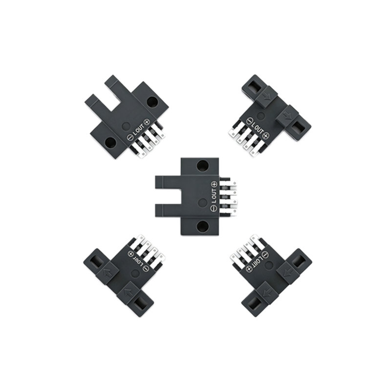
Pre-Wiring Safety and Preparation
Safety is paramount when working with electrical components. Always disconnect power from the control circuit before beginning any wiring work to prevent electric shock or equipment damage. Gather the necessary tools, including appropriate wire strippers, screwdrivers, and a multimeter for testing. Verify the sensor model and its specifications, particularly the operating voltage range (commonly 12-24V DC) and the output configuration (e.g., NPN or PNP transistor output). Ensure you have the correct cable type; shielded cables are often recommended to minimize electrical noise interference in industrial environments. Inspect the sensor and its connector for any physical damage. Proper preparation not only safeguards personnel but also enhances the longevity and reliability of the sensor system.
Identifying Terminal Connections
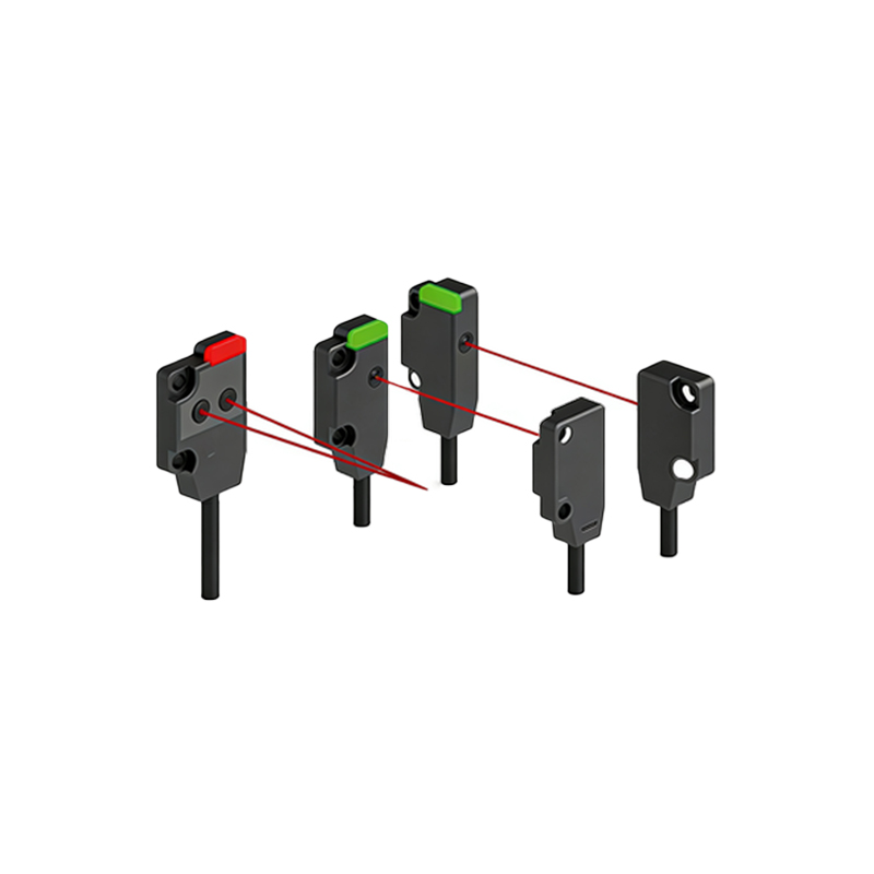
The R2M2 sensor typically features a standardized connector or terminal block with clearly labeled pins. Common terminals include:
- Brown wire (or +V): This is the positive power supply terminal. Connect it to the positive side of your DC power source within the specified voltage range.
- Blue wire (or 0V): This is the negative or ground terminal. Connect it to the negative side of the DC power source and the common ground of the control system.
- Black wire (or OUT): This is the output signal terminal. Its behavior depends on whether the sensor has an NPN (sinking) or PNP (sourcing) output. An NPN output switches the negative side, while a PNP switches the positive side. Connect this wire to the input of your controller, such as a PLC input module or a relay.
- White wire (or auxiliary function): Some models include an additional wire for functions like output inversion or a teach-in mode. Consult the specific datasheet for its use.
Accurate identification is critical for functional operation and preventing reverse polarity damage.
Step-by-Step Wiring Procedure
Follow this systematic procedure to wire your R2M2 sensor correctly:
1. Power Connection: First, connect the brown wire to the positive DC supply terminal (e.g., +24V) and the blue wire to the negative/ground terminal. Use ferrules or properly crimped terminals for a secure connection.
2. Output Connection: Connect the black output wire to the designated input point on your receiving device. For an NPN sensor, this typically means connecting the black wire to the PLC input, and the PLC input's common is connected to positive. For a PNP sensor, the PLC input common is connected to ground.
3. Shielding: If using a shielded cable, connect the shield braid to a functional earth ground point at the control panel end only. Do not connect it at both ends to avoid ground loops.
4. Load Consideration: Ensure the connected load (e.g., PLC input, relay coil) does not exceed the sensor's maximum output current rating.
5. Secure Connections: Tighten all terminal screws to the manufacturer's specified torque to prevent loose connections, which can cause overheating or intermittent failures.
Testing and Commissioning
After wiring is complete, do not immediately power the entire system. Perform a preliminary continuity check with a multimeter to ensure there are no short circuits. Once confirmed, apply power. The sensor usually has a status LED indicator. A steady or blinking green light often indicates proper power and standby operation. Test the sensing function by introducing a target object within its detection range. The output LED should activate, and the multimeter should show a voltage change at the output terminal corresponding to the sensor's logic (e.g., from 0V to ~24V for a PNP sensor). Verify that the signal is correctly received by the PLC or controller by monitoring its input status. Adjust the sensor's sensitivity or alignment if necessary to achieve reliable detection.
Troubleshooting Common Wiring Issues
Even with careful installation, issues may arise. Here are common problems and their solutions:
- No Power Indicator: Check the voltage at the sensor terminals with a multimeter. Verify polarity and ensure the power supply is functioning.
- Intermittent Operation: This is often caused by loose wiring connections or electrical noise. Re-tighten all terminals and ensure proper shield grounding. Keep sensor cables away from high-voltage power lines.
- Incorrect Output State: Confirm the output type (NPN/PNP) matches the input circuit of your controller. A mismatch will prevent proper signal reading. Also, check for wiring errors between the output wire and the load.
- Short Sensor Life: This can result from excessive supply voltage, incorrect load, or harsh environmental conditions. Always operate within the sensor's rated specifications.
Methodical troubleshooting helps maintain system uptime and sensor performance.
Best Practices for Optimal Performance
To ensure long-term reliability and accuracy of your R2M2 photoelectric sensor installation, adhere to these best practices:
- Always follow the manufacturer's installation guidelines provided in the manual.
- Use the correct wire gauge; typically, 18-22 AWG is suitable for low-current sensor circuits.
- Implement proper cable management. Use conduits or cable carriers in areas with moving machinery to prevent wear and tear.
- Consider environmental factors. For dusty or wet areas, select a model with an appropriate IP rating and ensure connectors are sealed.
- Periodically inspect and clean the sensor lens to prevent false triggers caused by dirt accumulation.
- Document your wiring diagrams and settings for future maintenance and troubleshooting reference.
Proper installation and maintenance are key to leveraging the full capabilities of photoelectric sensors in automation systems.