Introduction to Inductive Proximity Sensors
Inductive proximity sensors are fundamental components in modern industrial automation, providing non-contact detection of metallic objects. Their operation is based on the principle of electromagnetic induction. A high-frequency oscillating circuit generates an electromagnetic field from the sensor's active face. When a metallic target enters this field, eddy currents are induced on the target's surface. These eddy currents draw energy from the oscillator, causing a reduction in oscillation amplitude. This change is detected by a threshold circuit, which subsequently switches the sensor's output state. This robust operating principle makes them immune to environmental factors like dust, oil, and moisture, distinguishing them from optical or capacitive sensors. Their primary function is to detect the presence or absence of a metallic object without physical contact, making them ideal for harsh industrial environments where reliability is paramount.
Core Components and Material Selection
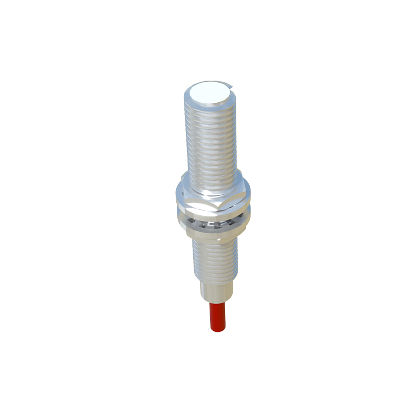
The manufacturing of a high-quality inductive sensor begins with the careful selection of materials for its core components. The heart of the sensor is the ferrite core, typically made from manganese-zinc or nickel-zinc ferrites. This material is chosen for its high magnetic permeability and low eddy current losses at high frequencies, ensuring a strong and stable electromagnetic field. The coil is wound from high-grade copper wire with precise insulation. The number of turns, wire gauge, and winding pattern are critical parameters calculated to achieve the desired sensing range and frequency response. The housing is usually constructed from stainless steel (e.g., V2A/AISI 304 or V4A/AISI 316 for corrosive environments) or nickel-plated brass, providing mechanical strength, environmental sealing (typically IP67 or IP69K), and shielding from external electromagnetic interference. The electronics, comprising the oscillator, demodulator, amplifier, and output switch, are built on a printed circuit board (PCB) using surface-mount technology (SMT) for compactness and reliability.
The Manufacturing Process: From Coil Winding to Assembly
The production line for inductive sensors is a blend of precision automation and skilled manual assembly. The process starts with the automated winding of the copper coil onto the ferrite core. This step requires extreme precision to ensure consistent inductance values. The wound coil is then potted with a thermally conductive epoxy resin to secure the windings, provide mechanical stability, and enhance heat dissipation. Simultaneously, the PCB is populated with microchips, resistors, capacitors, and the output transistor using high-speed SMT pick-and-place machines, followed by reflow soldering. The potted coil assembly is then soldered to the PCB. This sub-assembly is carefully inserted into the metal housing. A critical next step is the potting of the entire internal cavity with a specialized polyurethane or silicone compound. This potting process encapsulates the electronics, providing exceptional protection against vibration, shock, and thermal cycling, and is crucial for achieving the sensor's ingress protection rating.
Calibration, Testing, and Quality Assurance
After assembly, each sensor undergoes rigorous calibration and testing. This is a fully automated process. Sensors are placed on a test fixture where a standardized target (usually a square of mild steel) is moved towards the active face by a precision actuator. The exact distance at which the output switches is measured—this is the rated operating distance (Sn). The sensor's electronics are then automatically adjusted, often via laser-trimmed resistors or digital potentiometers, to ensure the sensing distance falls within a tight tolerance band (typically ±10% of Sn). Further tests include checking the switching frequency, repeat accuracy, hysteresis, temperature drift, and output current capability. Environmental stress screening, such as temperature cycling and vibration tests, is performed on sample batches from each production lot to validate long-term reliability and adherence to international standards like IEC 60947-5-2.
Key Design Considerations and Variants
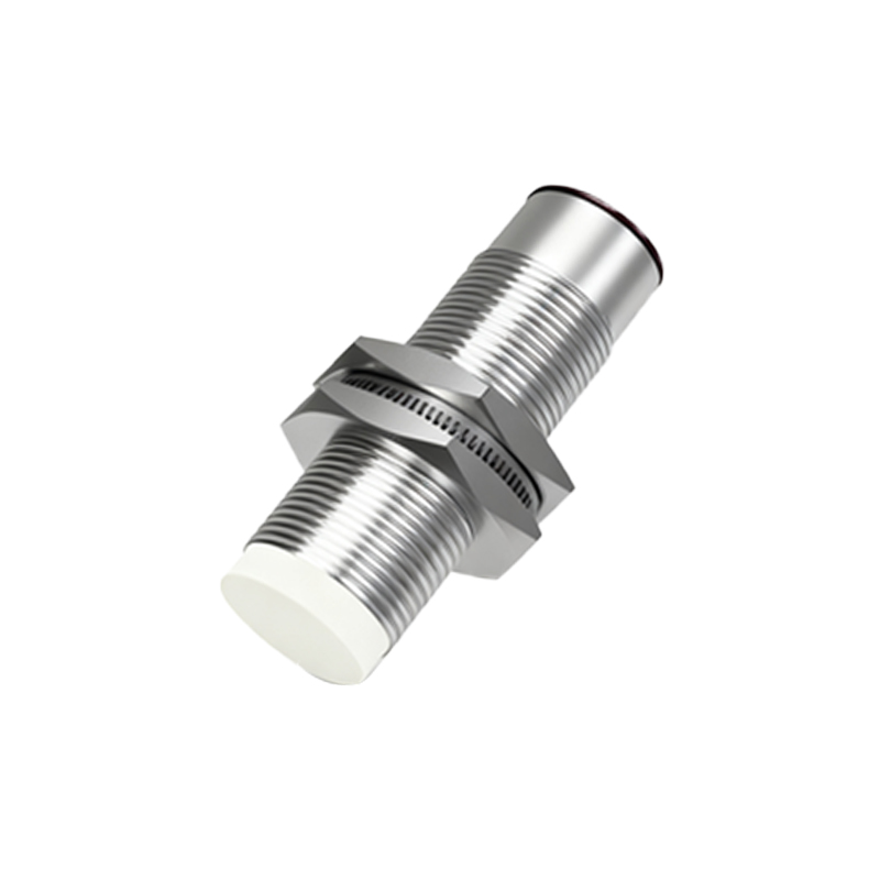
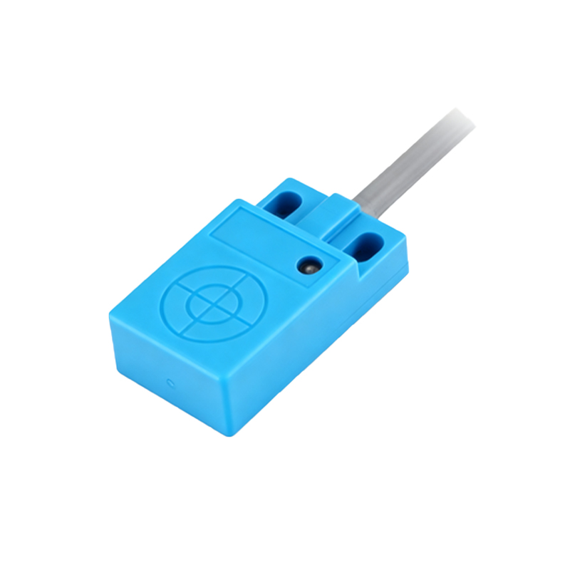
Manufacturing must accommodate various sensor designs to meet diverse application needs. Key design considerations include the sensing range, which is influenced by coil size, oscillator frequency, and target material (a factor of 1 for steel, less for stainless steel, aluminum, or copper). Housing shape is another critical factor; cylindrical threaded barrels (e.g., M8, M12, M18, M30) are most common, but rectangular and ring-shaped variants are also produced for specific mounting requirements. Output types are fundamentally either NPN (sinking) or PNP (sourcing) transistor configurations, with 3-wire or 4-wire (with a separate sense line) designs. Analog output sensors (0-10V or 4-20mA) that provide distance-proportional signals are manufactured on specialized lines. Additionally, weld-field immune models incorporate special filtering circuits to withstand the intense electromagnetic noise from resistance welding