Introduction to Proximity Sensing in Motion Control
In the realm of precision motion control, stepper motors are indispensable for applications requiring accurate positioning and repeatability. However, their reliable operation often hinges on ancillary components that provide critical feedback. Among these, proximity switch sensors play a pivotal role. These non-contact sensors detect the presence or absence of a target object, typically a metal flag or the motor shaft itself, and provide a definitive signal to the controller. This function is fundamental for establishing home positions, limiting travel to prevent mechanical damage, and confirming the completion of a move sequence. Unlike limit switches that require physical contact, proximity sensors offer enhanced reliability, longer lifespan, and faster response times, making them ideal for the demanding environments where stepper motors are deployed.
Core Operating Principles and Technologies
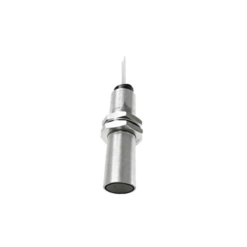
Proximity sensors for stepper motor systems primarily utilize inductive, capacitive, or Hall-effect technologies. Inductive sensors are the most common for metallic targets. They generate an oscillating electromagnetic field. When a ferrous or non-ferrous metal target enters this field, it induces eddy currents, causing a change in the oscillation amplitude. This change is detected by the sensor's circuitry, which then switches its output state. For non-metallic targets, capacitive sensors, which detect changes in capacitance caused by the target's presence, are employed. Hall-effect sensors, on the other hand, respond to magnetic fields and are often used to detect the position of a magnet mounted on the motor shaft or a moving carriage. The choice of technology depends on the target material, required sensing distance, environmental conditions, and cost considerations.
Key Specifications and Selection Criteria
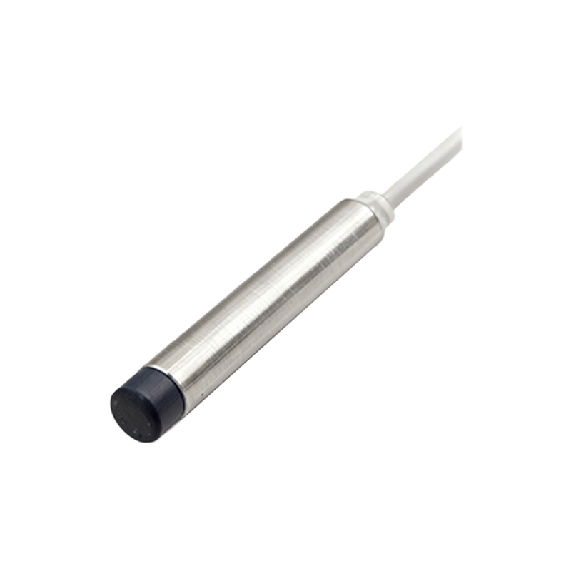
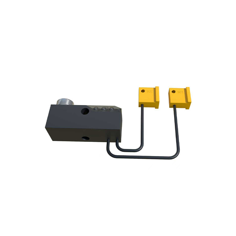
Selecting the correct proximity sensor requires careful analysis of several parameters. The sensing distance, or nominal range, is crucial and must account for installation tolerances and target approach direction. The sensor's housing style, such as cylindrical, rectangular, or slot-style, must fit the mechanical design. Output configuration is another critical decision; options include NPN (sinking) or PNP (sourcing) transistor outputs, and normally-open (NO) or normally-closed (NC) logic. The operating voltage, typically 10-30V DC for industrial sensors, must match the control system's power supply. Additionally, factors like switching frequency (response speed), temperature rating, and ingress protection (IP) rating for dust and moisture resistance must align with the application's demands. For stepper systems, repeatability—the sensor's ability to trigger at the exact same position consistently—is paramount for achieving high positioning accuracy.
Integration with Stepper Motor Controllers
The effective integration of a proximity sensor into a stepper motor control loop is a systems engineering task. The sensor's discrete output signal is wired to a dedicated input on the stepper motor driver or programmable logic controller (PLC). This input is often configured as a "home" or "limit" input. During a homing routine, the controller commands the motor to move until the sensor is activated, establishing a known reference point for all subsequent moves. For limit functions, the sensor signal immediately halts or reverses the motor to prevent over-travel. Modern controllers allow for sophisticated logic, such as using the sensor to trigger a controlled deceleration before a hard stop. Proper wiring, shielding to prevent electromagnetic interference from the motor coils, and correct signal conditioning are essential to avoid false triggers and ensure system robustness.
Common Applications and Use Cases
Proximity sensors find extensive use across industries employing stepper motors. In automated packaging machinery, they detect the presence of a product on a conveyor before a stepper-driven pusher or filler activates. In 3D printers and CNC machines, they define the machine's home position on each axis with extreme precision. Semiconductor manufacturing equipment uses them to verify the correct loading of wafers or reticles. In medical devices like automated analyzers, they ensure pipetting arms or sample trays are in their safe start positions. Robotic arms utilizing stepper motors for joint control often incorporate proximity sensors as end-of-travel limits to protect gears and linkages. Essentially, any application where knowing the absolute position of a stepper-driven component is critical for safety, accuracy, or process flow will benefit from these sensors.
Installation Best Practices and Troubleshooting
Correct installation is key to sensor performance. The sensor must be mounted securely to prevent vibration-induced misalignment. The sensing face should be parallel to the target's approach path, and the target should be large enough and made of the correct material to ensure reliable detection. Maintaining the specified gap between the sensor and the target is vital; too close may cause physical damage, while too far may lead to inconsistent triggering. Common issues include failure to detect, which