Introduction to Proximity Sensor Output Terminals
Proximity sensors are widely used in industrial automation for detecting the presence or absence of objects without physical contact. The output terminal of a proximity sensor is a critical component that transmits the detection signal to control systems, such as PLCs (Programmable Logic Controllers) or relays. Typically, the output is located on the sensor's housing, often integrated into a connector or cable assembly. Depending on the sensor type—inductive, capacitive, or photoelectric—the output configuration may vary, but it generally consists of wires or pins designated for power supply, ground, and the signal output. Understanding the exact location and wiring of these terminals is essential for proper installation and reliable operation in applications like machine safety, object counting, or position sensing.
Common Output Locations in Sensor Designs
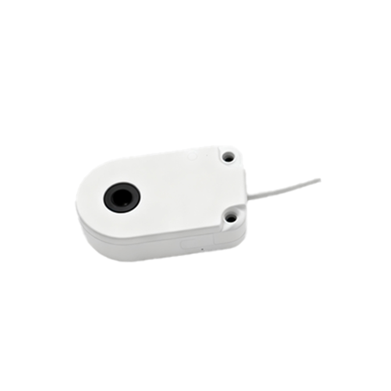
In most proximity sensors, the output terminals are situated at the rear or side of the device, opposite the sensing face. For cylindrical sensors, outputs are often found at the back end, where a cable is attached or a connector is mounted. Rectangular sensors might feature terminals on the top or side for easier access in tight spaces. Some models have built-in LED indicators near the output terminals to show status, such as power-on or detection activity. It's crucial to consult the sensor's datasheet or manual, as manufacturers like Omron, Siemens, or Schneider Electric may design outputs differently based on factors like environmental protection (e.g., IP ratings) or mounting requirements. For instance, waterproof sensors might have sealed output connections to prevent moisture ingress.
Wiring Configurations and Output Types
The output terminals correspond to specific wiring configurations, which define how the sensor interfaces with external devices. Proximity sensors commonly offer two output types: NPN (sinking) and PNP (sourcing). In NPN sensors, the output terminal connects to the load's negative side, while PNP sensors connect to the positive side. Additionally, analog outputs (e.g., 4-20 mA or 0-10 V) or digital outputs (switching signals) are available, each requiring distinct terminal connections. Typically, sensors have three or four wires: brown for positive voltage, blue for ground, black for output signal, and sometimes white for auxiliary functions. The output terminal is usually labeled on the sensor body or indicated in wiring diagrams, ensuring correct hookup to avoid damage or malfunction in systems like conveyor belts or robotic arms.
Factors Influencing Output Placement
Several factors determine where the output of a proximity sensor is located. Size constraints play a key role; compact sensors for space-limited applications may have outputs integrated into a micro-connector at the back. Environmental conditions, such as high temperatures or corrosive atmospheres, can lead to outputs being recessed or shielded within the housing. Industry standards, like IEC 60947-5-2, also influence design by specifying safety and performance requirements for output terminals. Moreover, user convenience is considered—some sensors feature quick-disconnect terminals for easy replacement without rewiring. In harsh environments, like automotive manufacturing, outputs might be located away from the sensing area to reduce exposure to vibrations or contaminants.
Installation and Maintenance Considerations
Properly locating and connecting the output terminals is vital for sensor longevity and accuracy. During installation, ensure the output wires are securely fastened and insulated to prevent short circuits or signal interference. Regular maintenance involves checking the terminal area for corrosion, loose connections, or physical damage, especially in high-vibration settings. If the output is part of a cable gland, inspect seals for integrity to maintain IP ratings. Troubleshooting output issues often starts at the terminals; using a multimeter to test voltage or continuity can help identify problems like faulty wiring or sensor failure. Always follow manufacturer guidelines for output handling to avoid downtime in automated processes.
Conclusion and Best Practices
In summary, the output of a proximity sensor is typically positioned on the housing, aligned with its wiring scheme and application needs. To optimize performance, always verify the output location via product documentation, choose the correct output type (NPN/PNP) for your control system, and implement robust wiring practices. By understanding these aspects, engineers can enhance reliability in industrial setups, from packaging machinery to assembly lines. As technology evolves, trends like IO-Link connectivity are integrating smart outputs, but the fundamental principle remains: the output terminal serves as the critical link between detection and action.